Transcription of 3.2 Darcy’s Law - New Mexico Tech: New Mexico Tech
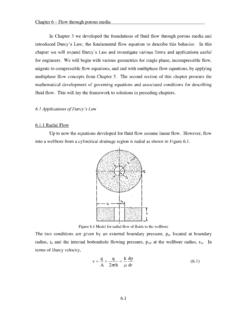
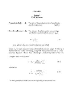
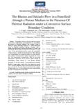
1 Chapter 3 Permeability darcy s Law In 1856, darcy investigated the flow of water through sand filters for water purification. His experimental apparatus is shown in Figure By empirical observation Figure Schematic of darcy s experiment on flow of water through sand. darcy noticed that fluid flow was directly proportional to the hydraulic gradient, resulting in the following equation, lhhKAq12 ( ) where q represents the volumetric flow rate of water downward through the cylindrical sand pack of cross-sectional area A and height l, h1 and h2 are the hydraulic head above the standard datum of the water in the manometer located at the input and output ports respectively, and K is a constant of proportionality found to be characteristic of the rock media.
2 It was observed that for any angle of the sandpack, a given constant flow rate would result in the same h; , Eq. ( ) is independent of the direction of flow. Fluid movement is due to the difference in potential energy. The two components of the potential energy are fluid pressure and elevation or gravity. By defining a relationship Chapter 3 Permeability between hydraulic head and pressure, it is possible to determine pressure at any point in the flow path. The total potential function per unit mass can be written as, ghgzp ( ) where g is the acceleration of gravity, p is pressure and is the density of the fluid and z is the elevation of a given point in the system. Substituting Eq. ( ) into Eq. ( ) and writing in differential form, we obtain, gzpdldAgKq ( ) The parameter, K is known as the hydraulic conductivity.
3 A sequence of experiments maintained at constant fluid potential gradient investigated the effect of different properties on the flow rate. The resulting expression for the hydraulic conductivity is, gcdK2 ( ) where d is grain diameter, is the fluid viscosity, and c is a constant of proportionality. Substituting into Eq. ( ) we get, dldzgdldpkAq ( ) where k is the permeability of the porous media. Equation ( ) is known as darcy s Law. It is applicable for steady state, laminar flow of an incompressible fluid, for a homogeneous and isotropic porous media. The negative sign in the previous equation is a result of the pressure and distance both measured positive in the same direction (see Fig. ). Therefore, the gradient within the bracket must be negative to move the flow in the same direction as the direction from high to lower potential.
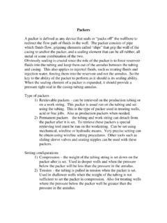
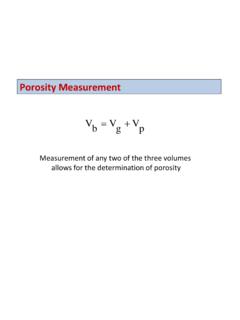
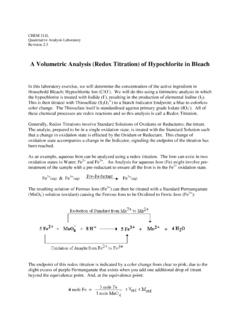
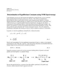
4 For example, take the simplified case of horizontal flow (z = 0), then since p1 > p2 the gradient must be LppdLdp12. Chapter 3 Permeability P1 P2 0 L q Figure Schematic of sign convention for potential gradient in horizontal flow For flow at any angle, , we can substitute sin for the elevation gradient; , dLdz sin. The sign convention is referenced such that positive is upward flow as shown in Figure dL dz Flow upward (+) sin 90 = 1 Flow downward sin -90 = -1 Figure Schematic of sign convention for any flow angle darcy s Law (Eq. ), written for any angle of flow becomes, singdldpkAq ( ) The dimensions of permeability can be determined by substituting for the appropriate cgs units found in table 222)/()2(32/)2(secLkTLmLTmLkTLcmcmdynepo isecmkcc Chapter 3 Permeability Units cgs darcy Field q flow rate cc/s cc/s Bpd A cross-sectional area cm2 cm2 ft2 L length cm cm Ft fluid viscosity poise centipoise Cp P pressure dyne/cm2 atm Psia density gm/cc gm/cc lbm/ft3 g gravity cm/s2 cm/s2 ft/s2 k - permeability cm2 darcy Md Table units used in petroleum engineering The unit for permeability in the cgs system is x 10-8 cm2.
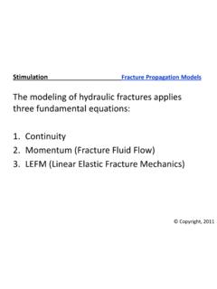
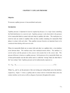
5 From a practical standpoint this measure is too small; therefore we define 1 darcy = x 10-12 m2 ( m)2. That is, a permeability of darcy is defined such that a single-phase fluid of cp flows at a rate of cc/sec/cm2 under a pressure of 1 atm/cm. In darcy units, Eq. ( ) becomes, ( ) Example Consider fresh water with a viscosity of cp and density of gm/cc, injected at a rate of 10 cc/sec through a sandpack with dimensions illustrated below. After steady state is achieved the pressure readings are recorded. Determine the permeability for this sandpack? Note: Barometric pressure = psi. d = 2 cm L = 5 cm Pin=10psig Pout=0psig Solution Since the core is horizontal the elevation term is zero; therefore Eq. ( ) is reduced to, Chapter 3 Permeability )5)(1( )1(10 Conversion to field units results in the following expression for darcy s Law, ( ) where is the specific gravity of the fluid.
6