Transcription of 3, 4, 5, 6 Ton Dual Capacity S - WaterFurnace
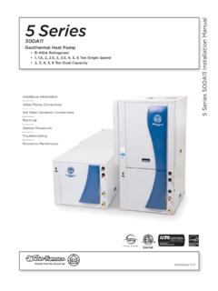
1 IM1300YS 07/17 Installation InformationWater Piping ConnectionsHot Water Generator ConnectionsElectricalStartup ProceduresTroubleshootingPreventive MaintenanceSynergy3D Installation ManualGeothermal Heat Pump with Water Heating for Radiant Floor Applications R-410A Refrigerant 3, 4, 5, 6 Ton Dual CapacitySynerg3 SYNERGY3D INSTALLATION MANUALT able of ContentsModel Nomenclature .. 4 General Installation Information .. 5 Closed Loop Ground Source Systems .. 9 Open Loop Ground Water Systems .. 10 Hot Water Generator Connections ..11 Typical Buffer Tank Installation ..11 Hydronic Section .. 12 Electrical Connections .. 14 Electronic Thermostat Installation .. 15 Auxiliary Heat.
2 16 Electrical and Blower Performance Data .. 17 Dimensional Data .. 18 Physical Data..20 Microprocessor Control .. 21 Operation Logic .. 25 Wiring Schematics ..26 Unit Startup..30 Operating Parameters.. 31 Pressure Drop .. 32 Compressor and Thermistor Resistance .. 33 Heat of Extraction/Rejection..34 Antifreeze Corrections .. 35 Correction Factor Tables ..36 Operating Limits, Reference Calculations, Legend and Notes .. 37 Troubleshooting ..38 Startup and Troubleshooting Form ..39 Heating and Cooling Analysis .. 40 Hot Water Cycle Analysis .. 41 Preventative Maintenance and Replacement Procedures ..42 Service Parts List ..43 Revision Guide .. 444 SYNERGY3D INSTALLATION MANUALM odel Nomenclature5 SYNERGY3D INSTALLATION MANUALF ilter Rack ConversionA 2 in.
3 MERV 11 filter is shipped with the heat pump. To field convert the filter rack to use 1 in. filters, simply insert the provided plastic push pins into the holes located in the filter rack. There are holes on the top and bottom of the rack, underneath the instruction labels, for field conversion to 1 in. Vertical UnitsPrior to setting the unit in place, remove and discard the compressor hold down shipping bolt located at the front of the compressor mounting units are available in left or right hand return configuration. Vertical units should be mounted level on a vibration absorbing pad slightly larger than the base to provide isolation between the unit and the floor. It is not necessary to anchor the unit to the floor (See Vertical Unit Mounting illustration).
4 Duct SystemAn air outlet collar is provided on vertical top flow units to facilitate a duct connection, which is shipped inside the unit. A flexible connector is recommended for discharge and return air duct connections on metal duct systems. Uninsulated duct should be insulated with a minimum of 1 in. duct insulation. Application of the unit to uninsulated ductwork in an unconditioned space is not recommended as the unit s performance will be adversely the unit is connected to existing ductwork, a previous check should have been made to assure that the duct has the Capacity to handle the air required for the unit application. If ducting is too small, as in the replacement of heating only systems, larger ductwork should be installed.
5 All existing ductwork should be checked for leaks and repaired when and StorageMove units in the normal Up orientation. Vertical units are not to be moved, but may be stored one upon another to a maximum height of two units. When the equipment is received, all items should be carefully checked against the bill of lading to be sure all crates and cartons have been received. Examine units for shipping damage, removing the units from the packaging if necessary. Units in question should also be internally inspected. If any damage is noted, the carrier should make the proper notation on the delivery receipt, acknowledging the damage. Unit LocationLocate the unit in an indoor area that allows easy removal of the filter and access panels, and has enough space for service personnel to perform maintenance or repair.
6 Provide sufficient room to make water, electrical and duct connection(s). If the unit is located in a confined space, such as a closet, provisions must be made for return air to freely enter the space by means of a louvered door, etc. Care should be taken when units are located in unconditioned spaces to prevent damage from frozen water lines and excessive heat that could damage electrical ConsiderationsInstallation and servicing of heating and air conditioning equipment can be hazardous due to system pressure and electrical components. Only trained and qualified service personnel should install, repair or service heating and air conditioning personnel can perform basic maintenance functions of cleaning coils and cleaning and replacing filters.
7 All other operations should be performed by trained service personnel. When working on air conditioning equipment, observe precautions in the literature, tags and labels attached to the unit and other safety precautions that may all safety codes. Wear safety glasses and work gloves. Use quenching cloth for brazing operations. Have fire extinguisher available for all brazing : Before performing service or maintenance operations on the system, turn off main power switches to the unit. Turn off accessory heater power switch if applicable. Electrical shock could cause serious personal : A minimum of 24 in. clearance should be allowed for access to front access AbsorbingMeshAir PadVertical Unit MountingGeneral Installation Information6 SYNERGY3D INSTALLATION MANUALThe duct system should be sized to handle the design airflow quietly.
8 To maximize sound attenuation of the unit blower, the supply and return plenums should include inter-nal duct liner of glass fiber or be of ductboard construction for the first few feet. If air noise or excessive airflow is a problem, the blower speed can be changed. See the Blower Performance and Blower Speed PipingThe proper water flow must be provided to each unit whenever the unit operates. To assure proper flow, use pressure/temperature ports to determine the flow rate. These ports should be located at the supply and return water connections on the unit. The proper flow rate cannot be accurately set without measuring the water pressure drop through the refrigerant-to-water heat exchanger.
9 All Synergy3D source water connections are swivel piping fittings that accept a 1 in. Male Pipe Thread (MPT) (see Female Locking Ring illustration). The swivel pipe connector has a rubber gasket seal similar to a garden hose gasket, which when mated to the flush end of 1 in. threaded pipe provides a leak-free seal without the need for thread sealing tape or compound. Check to ensure that the rubber seal is in the swivel connector prior to attempting any connection. The rubber seals are shipped attached to the water line. To make the connection to a ground loop system, mate the brass connector (supplied in CK4LI and CK4L-GLI connector kits) against the rubber gasket in the swivel connector, and thread the female locking ring onto the pipe threads, while maintaining the brass connector in the desired direction (see Female Locking RIng illustration).
10 Tighten the connectors by hand and then gently snug the fitting with pliers to provide a leak proof joint. When connecting to an open loop (ground water) system, thread 1 in. MPT fitting (schedule 80 PVC or copper) into the swivel connector and tighten in the same manner as noted above. The open and closed loop piping system must include pressure/temperature taps for use flexible hoses smaller than 1 in. inside diameter on the unit and limit hose length to 10 ft. per connection. Check carefully for water RingGasketSupportSleeveGasketMaterialFem ale Locking RingNOTE: Load side fittings are same type as : Water piping exposed to outside temperature may be subject to Installation Information INSTALLATION MANUALW ater QualityIt is the responsibility of the system designer and installing contractor to ensure that acceptable water quality is present and that all applicable codes have been met in these installations.
