Transcription of 3 ActiveAA Antena 11 - Active Antenna Amplifier
1 Amplifier for Small Magnetic and Electric Wideband receiving Antennas Model AAA-1 LZ1AQ 3. Antenna Contents Page Input Circuit of the Amplifier One loop and asymmetric vertical dipole Two loops in one plane and symmetric vertical dipole Two loops in orthogonal planes and symmetric vertical dipole Two loops in orthogonal planes and asymmetric dipole Two loops in one plane and symmetricl horizontal dipole 2/4 crossed parallel loops and symmetric vertical dipole Links Amplifier for Small Magnetic and Electric Wideband receiving Antennas Model AAA-1 LZ1AQ Input Circuit of the Amplifier There are two goals when designing a small wideband loop - low inductance and large area.
2 The construction of the loop should be made with the following rule in mind: the ratio of loop area to loop inductance should be maximized. That automatically means that a circular shape with 1 turn is the best choice. The material could be copper or aluminum actually the loop Q-factor is not important. The important factor is the low loop inductance. The conductor must be as fat as possible to reduce the loop inductance. Most of the commercial small loops on the market are circular in shape with diameter between to 1m. The material is aluminum tube of 10-30 mm diameter. To make such a loop is not trivial. We are suggesting a different approach by using cheap and available parts which are easy to mount. The loop parameters are not compromised because the so called parallel technique is used. The loops will not be described in details but basic configurations and a lot of figures will be given.
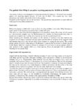
3 The loop size is not critical since these loops are aperiodic. The input circuit of the Amplifier is shown on Three antennas can be connected to the terminals two loops and a dipole. There are two jumpers which can connect the inputs of the voltage Amplifier to the loops which act as arms of a dipole. The relays are shown in off position which is dipole mode. In this mode the loop terminals are short circuited and fed to the corresponding input of the voltage Amplifier . If J1a and J1b are in OFF position a separate dipole can be connected to the connector CN1. Other combinations are possible J1a is ON, J1b is OFF - in this case V1 arm of a dipole is Loop A, another external arm or counterpoise should be connected at terminal V2. The GND terminal is used only for protective ground against lightning discharges.
4 Internally it is connected through a zener diode limiter to the Amplifier common point. In normal conditions it is closed and the Amplifier common point is left floating. Only when there is a strong EM field the zener diodes open thus limiting the common mode voltage. Connect this terminal only to a good ground point (a rod inserted into the ground or some other point which has a firm ground potential). If there is no such a point ( the user is living in an apartment) it is better to leave this terminal open. Amplifier for Small Magnetic and Electric Wideband receiving Antennas Model AAA-1 LZ1AQ The basic configuration of small loop/dipole Antenna which we will suggest is shown on and In the following sections we will describe different designs with increased complexity so the user can choose the most suitable Antenna for the particular environment.
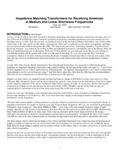
5 One Loop and Asymmetric Vertical dipole Connect Loop at +A, -A terminals. J1a=ON, J1b=OFF. Connect short counterpoise at V2 terminal. This is the simplest configuration. Recommended for quick test or for urban areas where the noise level is too high and better antennas will not give any advantages. Two modes are possible: Loop A and Vertical. The vertical dipole first arm is Loop A and the second arm is a counterpoise. If V2 is connected to ground then the vertical dipole becomes ground plane. Two basic mechanical loop designs will be described - the simplest lazy loop and a fat loop. Simple Lazy Loop Single turn loop with 6mm2 PVC insulated Cu wire A possible construction of the loop is shown on , , The mast is 20x 20 mm wood (or PVC tube). The loop is made from PVC insulated Cu 6 mm2 conductor.
6 The diameter of the loop is Three holes are drilled on the mast one at the top and two at the end of the loop. The conductor ends are inserted there. The loop ends are bent slightly and fixed with cable ties at the other side of the hole (this technique for leads connection is applied to all loops described later). The lower arm of the dipole (so called counterpoise) can be a piece of vertical wire with length around 1 m or a set of several ( 2 to 4) short horizontal radials with the length equal approximately to the radius of the loop. Theoretically the capacitance to ground of the upper and lower arms of the dipole should be equal to reduce the common mode interferences but in practice it is difficult to perform this measurement. Choose a convenient mechanical construction the length of the counterpoise is not critical at all.
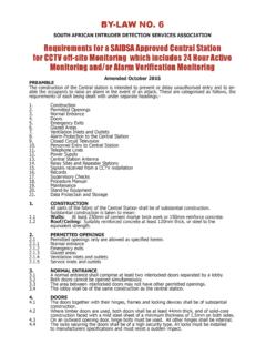
7 Amplifier for Small Magnetic and Electric Wideband receiving Antennas Model AAA-1 LZ1AQ Fig. Top of the loop Leads This loop is mechanically slightly flexible and might be bent by a very strong wind. A bare aluminum conductor with the diam. 3mm or more is better in this case. Above a diameter of m an additional horizontal wooden stick is needed (crest frame). Large Fat Loop On the market there are tubes for hot water heating systems which are very suitable for making loop Antenna . They are made from 3 layers - two polyethylene (PE) and one aluminum layers in the middle. These tubes are very lightweight and perfect thick loops can be made with them. The circular shape is formed easily since the tubes are flexible. A loop with diameter of 95 cm is shown on Fig.
8 Fig. Fig. A ( mm) type tube is used but the outer diameter is actually 15 mm. The mast is made from a PVC tube with 40 mm diameter. The connection of the loop leads is shown on Fig. , The tube can be cut easily with sharp knife. Amplifier for Small Magnetic and Electric Wideband receiving Antennas Model AAA-1 LZ1AQ Fig. Fig. Fig. The PE layers can be removed to some extent with hot soldering iron as shown on Then the aluminum surface of both sides must be carefully cleaned with sharp instrument. The terminal lug between aluminum and copper lead must be tinned to avoid electrochemical corrosion. Stainless steel screws with shake proof washers must be used for the same reason ( ). A plastic plate is used to fix the loop ends with 3mm screws ( ).
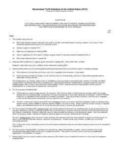
9 The plate is fixed to the mast with two 5 mm screws. The tube openings might be choked mechanically with caps or with hot melt adhesive. Be aware that PE cannot be stuck with standard glues! The inductance of this loop is uH and the area is m2. The loop is mechanically very stable and even bigger loops can be made from the same material. The total cost of the materials for this loop is about 3 4 Euro. Amplifier for Small Magnetic and Electric Wideband receiving Antennas Model AAA-1 LZ1AQ Two loops in one plane and symmetrical vertical dipole This is the basic loop/dipole design This is the basic suggested configuration. Loop A and Loop B are connected to the corresponding terminals CN2 and CN3 as shown on the J1a = J1b = ON. This is the basic recommended configuration . We have the following modes: Loop A, Loop B , Loop A & B in crossed parallel connection and vertical dipole where Loop A and B are the arms.
10 The first two modes will give identical results since the loops are in the same plane. Loops are made again from PVC insulated 6 mm2 Cu conductor. The diameter of each loop is To reduce the inductance of each loop, two parallel connected conductors are used (Fig. ). The measured inductance of each loop is uH. Fig. The loops are fixed with cable ties on both sides Amplifier for Small Magnetic and Electric Wideband receiving Antennas Model AAA-1 LZ1AQ The parallel conductors are connected together with a short wire and only one lead is passed to the box ( ). The leads are prepared as shown on and then soldered to the loops. Before soldering slightly bend the loop ends to fix them. Fig. The length of the leads should be at least 200 mm. Cut them to the exact length after mounting the Amplifier into the box.