Transcription of 3-Axis Digital Compass IC HMC5883L - Adafruit Industries
1 3-Axis Digital Compass IC HMC5883L The Honeywell HMC5883L is a surface-mount, multi-chip module designed for low-field magnetic sensing with a Digital interface for applications such as low-cost compassing and magnetometry. The HMC5883L includes our state-of-the-art, high-resolution HMC118X series magneto-resistive sensors plus an ASIC containing amplification, automatic degaussing strap drivers, offset cancellation, and a 12-bit ADC that enables 1 to 2 Compass heading accuracy. The I2C serial bus allows for easy interface. The HMC5883L is a surface mount 16-pin leadless chip carrier (LCC). Applications for the HMC5883L include Mobile Phones, Netbooks, Consumer Electronics, Auto Navigation Systems, and Personal Navigation Devices.
2 The HMC5883L utilizes Honeywell s Anisotropic Magnetoresistive (AMR) technology that provides advantages over other magnetic sensor technologies. These anisotropic, directional sensors feature precision in-axis sensitivity and linearity. These sensors solid-state construction with very low cross-axis sensitivity is designed to measure both the direction and the magnitude of Earth s magnetic fields, from milli-gauss to 8 gauss. Honeywell s Magnetic Sensors are among the most sensitive and reliable low-field sensors in the industry. FEATURES BENEFITS 3-Axis Magnetoresistive Sensors and ASIC in a LCC Surface Mount Package Small Size for Highly Integrated Products. Just Add a Micro- Controller Interface, Plus Two External SMT Capacitors Designed for High Volume, Cost Sensitive OEM Designs Easy to Assemble & Compatible with High Speed SMT Assembly 12-Bit ADC Coupled with Low Noise AMR Sensors Achieves 2 milli-gauss Field Resolution in 8 Gauss Fields Enables 1 to 2 Degree Compass Heading Accuracy Built-In Self Test Enables Low-Cost Functionality Test after Assembly in Production Low Voltage Operations ( to ) and Low Power Consumption (100 A)
3 Compatible for Battery Powered Applications Built-In Strap Drive Circuits Set/Reset and Offset Strap Drivers for Degaussing, Self Test, and Offset Compensation I2C Digital Interface Popular Two-Wire Serial Data Interface for Consumer Electronics Lead Free Package Construction RoHS Compliance Wide Magnetic Field Range (+/-8 Oe) Sensors Can Be Used in Strong Magnetic Field Environments with a 1 to 2 Degree Compass Heading Accuracy Software and Algorithm Support Available Compassing Heading, Hard Iron, Soft Iron, and Auto Calibration Libraries Available Fast 160 Hz Maximum Output Rate Enables Pedestrian Navigation and LBS Applications Advanced Information HMC5883L 2 SPECIFICATIONS (* Tested at 25 C except stated otherwise.)
4 Characteristics Conditions* Min Typ Max Units Power Supply Supply Voltage VDD Referenced to AGND VDDIO Referenced to DGND VDD+ Volts Volts Average Current Draw Idle Mode Measurement Mode ( Hz ODR; No measurement average, MA1:MA0 = 00) VDD = , VDDIO = (Dual Supply) VDD = VDDIO = (Single Supply) - - 2 100 - - A A Performance Field Range Full scale (FS) -8 +8 gauss Mag Dynamic Range 3-bit gain control 1 8 gauss Sensitivity (Gain) VDD= , GN=0 to 7, 12-bit ADC 230 1370 LSb/gauss Digital Resolution VDD= , GN=0 to 7, 1-LSb, 12-bit ADC milli-gauss Noise Floor (Field Resolution) VDD= , GN=0, No measurement average, Standard Deviation 100 samples (See typical performance graphs below) 2 milli-gauss Linearity gauss input range % FS Hysteresis gauss input range 25 ppm Cross-Axis Sensitivity Test Conditions.
5 Cross field = gauss, Happlied = 3 gauss %FS/gauss Output Rate (ODR) Continuous Measurment Mode Single Measurement Mode 75 160 Hz Hz Measurement Period From receiving command to data ready 6 ms Turn-on Time Ready for I2C commands Analog Circuit Ready for Measurements 200 50 s ms Gain Tolerance All gain/dynamic range settings 5 % I2C Address 8-bit read address 8-bit write address 0x3D 0x3C hex hex I2C Rate Controlled by I2C Master 400 kHz I2C Hysteresis Hysteresis of Schmitt trigger inputs on SCL and SDA - Fall (VDDIO= ) Rise (VDDIO= ) *VDDIO *VDDIO Volts Volts Self Test X & Y Axes Z Axis gauss X & Y & Z Axes (GN=5) Positive Bias X & Y & Z Axes (GN=5) Negative Bias 243 -575 575 -243 LSb Sensitivity Tempco TA = -40 to 125 C, Uncompensated Output %/ C General ESD Voltage Human Body Model (all pins) Charged Device Model (all pins)
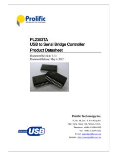
6 2000 750 Volts Operating Temperature Ambient -30 85 C Storage Temperature Ambient, unbiased -40 125 C HMC5883L 3 Characteristics Conditions* Min Typ Max Units Reflow Classification MSL 3, 260 C Peak Temperature Package Size Length and Width mm Package Height mm Package Weight 18 mg Absolute Maximum Ratings (* Tested at 25 C except stated otherwise.) Characteristics Min Max Units Supply Voltage VDD Volts Supply Voltage VDDIO Volts PIN CONFIGURATIONS Pin Name Description 1 SCL Serial Clock I2C Master/Slave Clock 2 VDD Power Supply ( to ) 3 NC Not to be Connected 4 S1 Tie to VDDIO 5 NC Not to be Connected 6 NC Not to be Connected 7 NC Not to be Connected 8 SETP Set/Reset Strap Positive S/R Capacitor (C2) Connection 9 GND Supply Ground 10 C1 Reservoir Capacitor (C1) Connection 11 GND Supply Ground 12 SETC S/R Capacitor (C2) Connection Driver Side 13 VDDIO IO Power Supply ( to VDD) 14 NC Not to be Connected 15 DRDY Data Ready, Interrupt Pin.
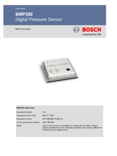
7 Internally pulled high. Optional connection. Low for 250 sec when data is placed in the data output registers. 16 SDA Serial Data I2C Master/Slave Data Table 1: Pin Configurations HMC5883L 4 Arrow indicates direction of magnetic field that generates a positive output reading in Normal Measurement configuration. PACKAGE OUTLINES PACKAGE DRAWING HMC5883L (16-PIN LPCC, dimensions in millimeters) MOUNTING CONSIDERATIONS The following is the recommend printed circuit board (PCB) footprint for the HMC5883L .
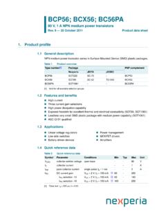
8 HMC5883L 5 8x 12 HMC5883 Land Pad Pattern(All dimensions are in mm) LAYOUT CONSIDERATIONS Besides keeping all components that may contain ferrous materials (nickel, etc.) away from the sensor on both sides of the PCB, it is also recommended that there is no conducting copper under/near the sensor in any of the PCB layers. See recommended layout below. Notice that the one trace under the sensor in the dual supply mode is not expected to carry active current since it is for pin 4 pull-up to VDDIO. Power and ground planes are removed under the sensor to minimize possible source of magnetic noise.
9 For best results, use non-ferrous materials for all exposed copper coding. HMC5883L 6 PCB Pad Definition and Traces The HMC5883L is a fine pitch LCC package. Refer to previous figure for recommended PCB footprint for proper package centering. Size the traces between the HMC5883L and the external capacitors (C1 and C2) to handle the 1 ampere peak current pulses with low voltage drop on the traces. Stencil Design and Solder Paste A 4 mil stencil and 100% paste coverage is recommended for the electrical contact pads.
10 Reflow Assembly This device is classified as MSL 3 with 260 C peak reflow temperature. A baking process (125 C, 24 hrs) is required if device is not kept continuously in a dry (< 10% RH) environment before assembly. No special reflow profile is required for HMC5883L , which is compatible with lead eutectic and lead-free solder paste reflow profiles. Honeywell recommends adherence to solder paste manufacturer s guidelines. Hand soldering is not recommended. Built-in self test can be used to verify device functionalities after assembly. External Capacitors The two external capacitors should be ceramic type construction with low ESR characteristics. The exact ESR values are not critical but values less than 200 milli-ohms are recommended. Reservoir capacitor C1 is nominally F in capacitance, with the set/reset capacitor C2 nominally F in capacitance.