Transcription of 3. BEAMS: STRAIN, STRESS, DEFLECTIONS The …
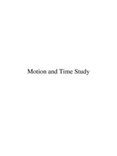
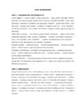
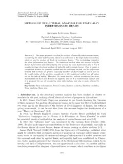
1 3. BEAMS: STRAIN, STRESS, DEFLECTIONSThe beam , or flexural member, is frequently encountered in structures andmachines, and its elementary stress analysis constitutes one of the more interesting facetsof mechanics of materials. A beam is a member subjected to loads applied transverse tothe long dimension, causing the member to bend. For example, a simply-supported beamloaded at its third-points will deform into the exaggerated bent shape shown in Fig. proceeding with a more detailed discussion of the stress analysis of beams,it is useful to classify some of the various types of beams and loadings encountered inpractice.
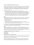
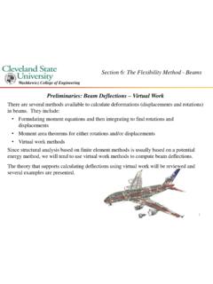
2 Beams are frequently classified on the basis of supports or reactions. A beamsupported by pins, rollers, or smooth surfaces at the ends is called a simple beam . Asimple support will develop a reaction normal to the beam , but will not produce a momentat the reaction. If either, or both ends of a beam projects beyond the supports, it is calleda simple beam with overhang. A beam with more than simple supports is a continuousbeam. Figures , , and show respectively, a simple beam , a beam withoverhang, and a continuous beam .
3 A cantilever beam is one in which one end is built intoa wall or other support so that the built-in end cannot move transversely or rotate. Thebuilt-in end is said to be fixed if no rotation occurs and restrained if a limited amount ofrotation occurs. The supports shown in Fig. , and represent a cantileverbeam, a beam fixed (or restrained) at the left end and simply supported near the other end(which has an overhang) and a beam fixed (or restrained) at both ends, beams and simple beams have two reactions (two forces or one forceand a couple) and these reactions can be obtained from a free-body diagram of the beamby applying the equations of equilibrium.
4 Such beams are said to be staticallydeterminate since the reactions can be obtained from the equations of and other beams with only transverse loads, with more than two reactioncomponents are called statically indeterminate since there are not enough equations ofequilibrium to determine the Example of a bent beam (loaded at its third points) Various types of beams and their deflected shapes: a) simple beam , b) beamwith overhang, c) continuous beam , d) a cantilever beam , e) a beam fixed (or restrained)at the left end and simply supported near the other end (which has an overhang), f) beamfixed (or restrained) at both the deflection shape of Fig.
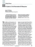
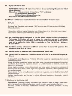
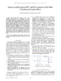
5 , it is possible to observe thatlongitudinal elements of the beam near the bottom are stretched and those near the topare compressed, thus indicating the simultaneous existence of both tensile andcompressive stresses on transverse planes. These stresses are designated fibre orflexural stresses. A free body diagram of the portion of the beam between the left end andplane a-a is shown in Fig. A study of this section diagram reveals that a transverseforce Vr and a couple Mr at the cut section and a force, R, (a reaction) at the left supportare needed to maintain equilibrium.
6 The force Vr is the resultant of the shearing stressesat the section (on plane a-a) and is called the resisting shear and the moment, Mr, is theresultant of the normal stresses at the section and is called the resisting Section of simply supported magnitudes and senses of Vr and Mr may be obtained form the equations ofequilibrium Fy=0 and MO=0 where O is any axis perpendicular to plane xy (thereaction R must be evaluated first from the free body of the entire beam ). For the presentthe shearing stresses will be ignored while the normal stresses are studied.
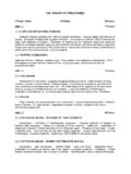
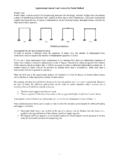
7 Themagnitude of the normal stresses can be computed if Mr is known and also if the law ofvariation of normal stresses on the plane a-a is known. Figure shows an initiallystraight beam deformed into a bent segment of the bent beam in Fig. is shown in Fig. with the distortion highlyexaggerated. The following assumptions are now madei) Plane sections before bending, remain plane after bending as shown in Fig. (Note that for this to be strictly true, it is necessary that the beam be bent only with couples ( , no shear on transverse planes), that the beam must be proportioned such that it will not buckle and that the applied loads are such that no twisting Initially straight beam and the deformed bent Distorted section of bent beamii) All longitudinal elements have the same length such the beam is initially straight and has a constant cross ) A neutral surface is a curved surface formed by elements some distance, c, from the outer fibre of the beam on which no change in length occurs.
8 Theintersection of the neutral surface with the any cross section is the neutral axis of the strain is not usually required for engineering evaluations (for example,failure theories), it is used in the development of bending relations. Referring to Fig. ,the following relation is observed: yy = cc( )where y is the deformation at distance y from the neutral axis and c is the deformationat the outer fibre which is distance c from the neutral axis. From Eq. , the relation forthe deformation at distance y from the neutral axis is shown to be proportional to thedeformation at the outer fibre: y = ccy( )Since all elements have the same initial length, x, the strain at any element canbe determined by dividing the deformation by the length of the element such that: y x =yc c x =yc c( ) Undeformed and deformed elementsNote that is the in the strain in the x direction at distance y from the neutral axis and that = x.
9 Note that Eq. is valid for elastic and inelastic action so long as the beam doesnot twist or buckle and the transverse shear stresses are relatively alternative method of developing Eq. involves the definition of normal incremental element of a beam is shown both undeformed and deformed in Fig. once again that any line segment x located on the neutral surface does notchanges its length whereas any line segment s located at the arbitrary distance y fromthe neutral surface will elongate or contract and become s' after deformation. Then bydefinition, the normal strain along s is determined as: =lim s 0 s' s s( )Strain can be represented in terms of distance y from the neutral axis and radius ofcurvature of the longitudinal axis of the element.
10 Before deformation s= x but afterdeformation x has radius of curvature with center of curvature at point O'. Since defines the angle between the cross sectional sides of the incremental element, s= x= . Similarly, the deformed length of s becomes s'= y() .Substituting these relations into Eq. gives: =lim 0 y() ( ) can be arithmetically simplified as = y/ . Since the maximum strainoccurs at the outer fibre which is distance c from the neutral surface, max= c/ = c,the ratio of strain at y to maximum strain is max= y/ c/ ( )which when simplified and rearranged gives the same result as Eq.