Transcription of 3-Channel, 8-Bit, PWM LED Driver with Single-Wire ...
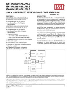
1 SDOGNDGNDVCCC ontrollerOUT0 SDOSDIVCCTESTOUT1 OUT2 DeviceVLEDOUT0 SDIVCCGNDTESTOUT1 OUT2 DeviceOptionalOPENor GNDLEDLampPowerSupplyDevice andControllerPowerSupplyOPENor GNDO ptionalProductFolderSample &BuyTechnicalDocumentsTools &SoftwareSupport &CommunityAn IMPORTANTNOTICEat the end of this datasheetaddressesavailability,warranty, changes,use in safety-criticalapplications,intellectual propertymattersand FEBRUARY2013 REVISEDOCTOBER2016 TLC597313-Channel,8-Bit, PWM LED DriverWith single -WireInterface(EasySet)11 Features1 ThreeSinkCurrentChannels CurrentCapability: 50 mA per Channel Grayscale(GS)ControlWithPWM: 8-Bit(256 Steps)WithSimpleGammaCorrection single -WireInterface(EasySet ) Power-Supply(VCC)VoltageRange: No InternalShuntRegulatorMode:3 V to V InternalShuntRegulatorMode:3 V to 6 V OUTT erminalsMaximumVoltage:Up to 21 V IntegratedShuntRegulator DataTransferMaximumRate: Bits per Second(bps):600 kbps InternalGS ClockOscillator:6 MHz(Typical) kHz (Typical) OutputDelaySwitchingto PreventInrushCurrent UnlimitedDeviceCascading OperatingTemperature.
2 40 C to 85 C2 ApplicationsRGBLEDC lusterLampDisplays3 DescriptionThe TLC59731deviceis an easy-to-use, 3-Channel, 50-mAsink Single-Wire ,600-kbpsserialinterface(Easy Set)providesa LEDdriverprovides8-bitpulsewidthmodulati on(PWM) displayrepeatrate is achievedat kHz (typical) with an integrated6-MHzgrayscale(GS) set by eachexternalresistorconnectedto the OUTnterminalin TLC59731has an internalshuntregulatorthatcan be usedfor (1)PARTNUMBERPACKAGEBODYSIZE(NOM)TLC5973 1 SOIC(8) (1) For all availablepackages,see the orderableaddendumatthe end of the (No InternalShuntRegulatorMode)2 TLC59731 SBVS222C FEBRUARY2013 :TLC59731 SubmitDocumentationFeedbackCopyright 2013 2016,TexasInstrumentsIncorporatedTableof Contents1 Pin Configurationand Applicationand 's and Don' Deviceand Mechanical,Packaging,and RevisionHistoryNOTE:Pagenumbersfor previousrevisionsmay differfrompagenumbersin the (October2015)to RevisionCPage ChangedtheGrayscale(GS)Controldescriptio nfor ChangedGrayscale(GS)Function(PWMC ontrol)section.
3 Correctednumberof bits throughoutsectionandcorrectedTable2 Added2nd sentenceto 3rd paragraphofGrayscale(GS)Function(PWMC ontrol) ChangedthePWMC ontrolsectionto accountfor a 24-bitGS datalatchinsteadof a DeletedtheOne-WireInterface(EasySet) (April2013)to RevisionBPage AddedPin Configurationand Functionssection,ESDR atingstable,FeatureDescriptionsection,De viceFunctionalModes,Applicationand Implementationsection,PowerSupplyRecomme ndationssection,Layoutsection,Deviceand DocumentationSupportsection,andMechanica l,Packaging,and AddedGrayscale(GS)Control,EasySetand ShuntRegulator, andNo ChangedConnectorDesigntitle ..13 ChangedFigure12: changedOUTntracesGSDATA= 4093and GSDATA= FEBRUARY2013 REVISEDOCTOBER2016 ProductFolderLinks:TLC59731 SubmitDocumentationFeedbackCopyright 2013 2016,TexasInstrumentsIncorporatedChanges fromOriginal(February2013)to RevisionAPage Changedbps valuein Changedbps ChangedAC Characteristics,fCLK(SDI)parametermaximu mspecificationin 5 ChangedICC1parametertest ChangedsecondparagraphofGrayscale(GS)Fun ction(PWMC ontrol) ChangedDataTransferRate(tCYCLE) FEBRUARY2013.
4 TLC59731 SubmitDocumentationFeedbackCopyright 2013 2016,TexasInstrumentsIncorporated5 Pin Configurationand FunctionsD Package8-PinSOICTop ViewPin be configuredin parallelto increasethe sink be appliedto pin is internallypulleddownto GNDwith a 1-M (typical) TI internaltest pin mustbe connectedto GNDor left Power-supplyvoltage(1)Stressesbeyondthos elistedunderAbsoluteMaximumRatingsmay causepermanentdamageto the stressratingsonly,whichdo not implyfunctionaloperationof the deviceat theseor any otherconditionsbeyondthoseindicatedunder RecommendedOperatingConditions. Exposureto absolute-maximum-ratedconditionsfor extendedperiodsmay affectdevicereliability.(2)All voltagesare with respectto (unlessotherwisenoted)(1)MINMAXUNITV oltage(2)Supply,VCCVCC ,VINSDI + ,VOUTOUT0to OUT2 (DC),IOUTOUT0to OUT2060mATemperatureOperatingjunction,TJ 40150 CStoragetemperature,Tstg 55150(1)JEDEC documentJEP155statesthat 500-VHBM allowssafe manufacturingwith a standardESDcontrolprocess.
5 (2)JEDEC documentJEP157statesthat 250-VCDM allowssafe manufacturingwith a (ESD)ElectrostaticdischargeHumanbodymode l(HBM),per ANSI/ESDA/JEDECJS-001(1) 8000 VCharged-devicemodel(CDM),per JEDEC specificationJESD22-C101(2) FEBRUARY2013 REVISEDOCTOBER2016 ProductFolderLinks:TLC59731 SubmitDocumentationFeedbackCopyright 2013 2016, CHARACTERISTICSVCCS upplyvoltageNo outputOUT0to VCCVIOHHigh-leveloutputcurrentSDO 2mAIOLLow-leveloutputcurrentSDO2mAOUT0to OUT250 IREGS huntregulatorsink currentVCC20mATAO peratingfree-airtemperaturerange 40+85 CTJO peratingjunctiontemperaturerange 40+125 CAC CHARACTERISTICSfCLK(SDI)Datatransferrate SDI20600kHztSDISDI / fCLKnstWHPulseduration,highSDI14nstWLPul seduration,lowSDI14nstH0 Holdtime:end of sequence(EOS)SDI to SDI / / fCLK stH1 Holdtime:datalatch(GSLAT)SDI to SDI 8 / fCLK s(1)For moreinformationabouttraditionaland new thermalmetrics,see theSemiconductorand IC (1)TLC59731 UNITD (SOIC)8 PINSR C/WR JC(top)Junction-to-case(top) C/WR C/W C/W C/WR JC(bot)Junction-to-case(bottom)thermalre sistanceN/A C/WtH0H1, t50%tW HtW LVCCGNDtWHW L, tSDI(1)SDI(1)t , tH0H150%32nd Data1st Data of Next Device (tcase) or1st Data of Next Sequence (tcase).
6 H0H1 VCCGND6 TLC59731 SBVS222C FEBRUARY2013 :TLC59731 SubmitDocumentationFeedbackCopyright 2013 2016, TA= 40 C to +85 C, VCC= 3 V to V, and CVCC= F. Typicalvaluesat TA= 25 C and VCC= V, (SDO)IOH= 2 mAVCC (SDO)IOL= 2 (VCC)ICC= 1 mA, SDI = (VCC)VCC= 3 V to V, SDI = low, all grayscale(GSn) = FFh,VOUTn= V, SDO= 15 3 V to , SDI = 600 kHz,GSn=FFh,VOUTn= V, SDO= 15 (OUT0to OUT2)All OUTn= on, VOUTn= V3240mAIOLKGO utputleakagecurrent(OUT0to OUT2)GSn= 00h,VOUTn= 21 VTJ= 40 C to +85 ATJ= +85 C to+125 (SDI)At SDI1M TA= 40 C to 85 C, VCC= V to V, CL= 15 pF, RL= 110 , and VLED= 5 V, at TA= 25 C and VCC= 5 (on off)200400nstF0 Fall timeSDO2612nstF1 OUTn(off on)200400nstD0 PropagationdelaySDI to SDO 3050nstD1 OUT0 to OUT1 , OUT1 to OUT2 ,OUT0 to OUT1 , OUT1 to OUT2 25nstWOShiftdataoutputone pulsedurationSDO to SDO 75125250nsfOSCI nternalGS oscillatorfrequency468 MHz(1)
7 Inputpulserise and fall time is 1 ns to 3 InputTiming90%10%VOUTnHVOUTnLVOUTnHVOUTn L50%50%tD1t , t ,R1F1D1tOUTnOUTn+ 1tD1tF1tR190%10%tR0 VOHVOLVCCGND50%50%tD0t , t ,R0F0D0W 0t , tSDI(1) FEBRUARY2013 REVISEDOCTOBER2016 ProductFolderLinks:TLC59731 SubmitDocumentationFeedbackCopyright 2013 2016,TexasInstrumentsIncorporated(1)Inpu tpulserise and fall time is 1 ns to 3 OutputTimingtR1tF0fCLK(SDI)SDISDOtD0tD1t D1 OUT0 ONOFFONOFFONOFFtF1(V)OUTnH(V)OUTnLOUT1 OUT2 VCCData TransferPeriod Memory(Internal in all Devices)1st Device1st Data (0)fCLK(SDI)Data transfer period (tCYCLE) is Signal(Internal)Low = SDI data are not output from Signal(Internal in 1st Device)32-Bit Shift Register MSB(Internal in 1st Device)32-Bit Shift Register MSB-1(Internal in 1st Device)32-Bit Shift Register LSB+1(Internal in 1st Device)Recognized Data,SIN Signal(Internal in 1st Device)32-Bit Shift Register LSB(Internal in 1st Device)GSLAT Signal(Internal in 1st Device)New GS DatatR0(All GS data are 0 when VCC powers up.)
8 Data transfer period (tCYCLE) is (0)3rdData (1)4thData (1)5thData (1)32ndData (0)2nd Device1st Data (0)2ndData (0)32ndData (0)1st Device1st Data (0)1st Data (0)31stData32nd Data (0)4th Data (1)3rd Data (1)2nd Data (0)5th Data (1)1st Data (0)4th Data (1)3rd Data (1)2nd Data (0)5th Data (1)4th Data (1)1st Data (0)3rd Data (1)2nd Data (0)1st Data (0)1st Data (0)32nd Data (0)3rd Data (0)2nd Data (0)(1)(1)(1)SCLK Signal(Internal in 2nd Device)32nd Data31stData31st Data2nd Data (0)1st Data (0)30thDataHigh = SDI data are output from Data (0)(All GS data are 0 when VCC powers up.)1st Data (0)32nd Data (0)New GS DataGS Data Latch(Internal in 1st Device)24-Bit GS Data Latch(Internal in 2nd Device)GSLAT Signal(Internal in 2nd Device)32-Bit Shift Register LSB(Internal in 2nd Device)t(for EOS)H0t(for GSLAT)H18 TLC59731 SBVS222C FEBRUARY2013 :TLC59731 SubmitDocumentationFeedbackCopyright 2013 2016,TexasInstrumentsIncorporated(1)OUTn ON-timechanges,dependingon the datain the 24-bitGS DataWriteand 0 10 20 30 40 50 Output Voltage (V) Output Current (mA) Ta = 40 Ta = +25 Ta = +85 C001 TA = 40 C TA = +25 C TA = +85 C FEBRUARY2013 REVISEDOCTOBER2016 ProductFolderLinks:TLC59731 SubmitDocumentationFeedbackCopyright 2013 2016, TA= 25 C and VCC= 12 V (unlessotherwisenoted)Figure4.
9 OutputCurrentvs OutputVoltage(Outn)VCCVCCGNDSDOCL(1)VCCV CCGNDOUTn(1)RLCL(2)VLEDOUTn(1)GNDVCCSDOG NDVCCSDIGND10 TLC59731 SBVS222C FEBRUARY2013 :TLC59731 SubmitDocumentationFeedbackCopyright 2013 2016,TexasInstrumentsIncorporated7 OutputSchematicDiagramsFigure5. SDIF igure6. SDO(1)n = 0 to (1)n = 0 to 2.(2) RiseTimeand Fall TimeTestCircuitforOutn(1) RiseTimeand Fall TimeTestCircuitforSDOC ommandDecoder (3Ah)InterfaceControl83 Upper 8 BitsSDOGND32-Bit Shift Register24-Bit GS Data LatchGS ClockCounter3-Channel Sink DriverSwitching DelayLSBMSB031 LSBMSB023 VCCSDI24 OUT2 UVLOS huntRegulatorresetInternalOscillator8-Bi t PWM Timing Controlwith Simple Gamma CorrectionOUT0 OUT1 VCCsinsclk6 MHz3 Lower 24 FEBRUARY2013 REVISEDOCTOBER2016 ProductFolderLinks:TLC59731 SubmitDocumentationFeedbackCopyright 2013 2016,TexasInstrumentsIncorporated8 TLC59731is a an individually-adjustable,256-step,pulse-w idthmodulation(PWM)grayscale(GS) dataare inputthrougha serialsingle- wire TLC59731has a maximumcurrentvalueof eachchannelis determinedby TLC59731can functionwithoutexternalCLKsignalsbecause the deviceis integratedwitha integratedwitha shuntregulatorthat can be usedfor < RVCC<V(V) VLED-8 mAV(V) VLED-6 mAOptional+5 VSDOGNDC ontrollerVLEDOUT0 SDIVCCGNDTESTOUT1 OUT2( F)mRL0 PowerSupplyRVCCCVCC( F)mRVCCCVCC1st DeviceRL1RL2VF_TOTALSDOOUT0 SDIVCCGNDTESTOUT1 OUT22nd DeviceRL0RL1RL2 OpenorGNDO penorGNDRLn( ) =WV(V) V(V) V(V)LEDF_TOTALOUTn--IOUTn(mA)I(mA) =OUTnV(V) V(V) V(V)
10 LEDF_TOTALOUTn--R ( )LnW12 TLC59731 SBVS222C FEBRUARY2013 :TLC59731 SubmitDocumentationFeedbackCopyright 2013 2016, typicalsink currentvalueof eachchannel(IOUTn) can be set by resistor(RLn) that is placedbetweenthe LEDcathodeand OUTnpins;see Figure10. The typicalsink currentvaluecan be calculatedby Equation1 and thetypicalresistorvaluecan be calculatedby n = 0 to 2(1)where n = 0 to 2 VLED= the LEDanodevoltage VF_TOTAL= the total LEDforwardvoltage VOUTn= the OUTnoutputvoltage(2)Notethat the typicalVOUT nvalueis V with a 40-mAoutputcurrent,as shownin CapacitorValueSettingfor ShuntRegulatorThe TLC59731internallyintegratesa shuntregulatorto showsan applicationcircuitthat usesthe internalshuntregulatorthrougha resistor,RVCC. The recommendedRVCC valuecan becalculatedby Equation3.