Transcription of 3 O-Ring Basics - applerubber.com
1 3 O-Ring Basics Seal Thinking Dimensional Considerations Elastomer seals are unlike any other materials that Inside Diameter design engineers confront. Metal or plastic parts, for To provide an effective seal, the O-Ring 's inside instance, are probably failing if visibly distorted. But, diameter ( ) must be smaller than the piston groove an O-Ring MUST be deformed to function properly. In diameter, so that the O-Ring is slightly stretched, fitting fact, an O-Ring that is not squeezed and stretched in snugly in the groove. This stretch should be between its application is the wrong O-Ring . 1%-5% with 2% as the ideal in most applications. A stretch greater than 5% is not recommended. Definition The resulting stress on the O-Ring will cause An O-Ring is a doughnut-shaped object or torus. accelerated aging and cross section reduction. The opposite sides of an O-Ring are squeezed between Exception to this rule is a floating seal. These are the walls of the cavity or gland into which the O-Ring O-rings that are allowed to sit in grooves freely or is installed.
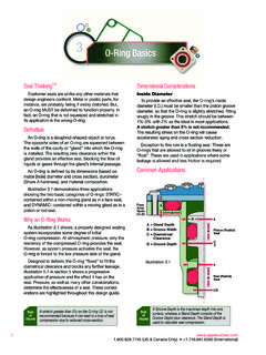
2 The resulting zero clearance within the float . These are used in applications where some gland provides an effective seal, blocking the flow of leakage is allowed and less friction is required. liquids or gases through the gland's internal passage. An O-Ring is defined by its dimensions (based on Common Applications inside [hole] diameter and cross section), durometer (Shore A hardness), and material composition. Illustration demonstrates three applications showing the two basic categories of O-rings: STATIC . contained within a non-moving gland as in a face seal, and DYNAMIC contained within a moving gland as in a Face A. Axial piston or rod seal. Seals B. (C=0). Why an O-Ring Works D A. A = Gland Depth As Illustration shows, a properly designed sealing B = Groove Width Piston (Radial). B. system incorporates some degree of initial C = Diametrical Seal O-Ring compression. At atmospheric pressure, only the Clearance C. resiliency of the compressed O-Ring provides the seal.
3 D = Groove Depth 2. However, as system pressure activates the seal, the O-Ring is forced to the low pressure side of the gland. Designed to deform, the O-Ring flows to fill the Illustration A. diametrical clearance and blocks any further leakage. Illustration in section 5 shows a progressive application of pressure and the effect it has on the Rod (Radial). B Seal seal. Pressure, as well as many other considerations, determine the effectiveness of a seal. These consid . C/2. erations are highlighted throughout this design guide. A Groove Depth is the machined depth into one Rule A stretch greater than 5% on the O-Ring is not Rule of of surface, whereas a Gland Depth consists of the recommended because it can lead to a loss of seal Thumb Thumb Groove Depth plus clearance. The Gland Depth is compression due to reduced cross-section. used to calculate seal compression. 7 (US & Canada Only) + (International). 3. Calculate the O-Ring according to the following Calculation of Maximum formula: O-Ring Cross Section: O-Ring = Groove Diameter 1.
4 Enter the BORE DIAMETER. % of stretch desired + 1 2. Subtract the BORE tolerance from the ( 1% - 5% ) BORE DIAMETER. Example 3. Enter the GROOVE DIAMETER. If Groove Diameter = .231 4. Add the GROOVE tolerance to the Then O-Ring = .231 = .229 to .220 GROOVE DIAMETER. to 5. Subtract line 4 from line 2. Depending on % of stretch desired 6. Divide line 5 by 2. Cross Section 7. Enter the MAXIMUM % COMPRESSION. When calculating the cross section ( ) of an O-Ring , 8. Divide line 7 by 100. you need to consider the size of the gland to be filled as 9. Subtract line 8 from the number 1. well as the amount of squeeze needed to create a good 10. Divide line 6 by line 9. seal. Virtually every gland has a slight gap between the 11. Enter O-Ring TOLERANCE. two mating surfaces, termed diametrical clearance.. 12. Subtract line 11 from line 10 for the answer Therefore, it is important for the O-Ring cross-section to be greater than the gland height. The resulting O-Ring Maximum O-Ring CS =.
5 Squeeze prevents leakage by blocking the diametrical gap. Illustration demonstrates that in static face seals Min Bore Diameter - Max Groove Diameter 2. or dynamic piston and rod seals, the O-Ring is being O-Ring CS Tolerance squeezed slightly within the gland. Squeeze may occur 1- Maximum % Compression 100. in one of two possible ways. If the squeeze occurs on the top and bottom surfaces of the O-Ring , as in face seals, it is referred to as AXIAL squeeze. If the squeeze is on the inner and outer surfaces of the O-Ring , as in Radial Seal 2. piston or rod seals, it is referred to as RADIAL squeeze. To obtain the correct amount of squeeze for optimum O-Ring sealing, careful consideration must be given to the size of the O-Ring in relation to the size of the glandular space into which the O-Ring is being installed. The actual calculation for the cross section needed in an O-Ring varies depending on whether it will be used in a dynamic or static application.
6 In a dynamic situation, lower squeeze is recommended to reduce friction. Dynamic (Moving) Radial Seal Cross Section Calculation Illustration Referring to Illustration for term definition, and Illustration for sample dimensions, calculating the correct O-Ring cross section for a specific gland depth is illustrated to the right. In the case of the dynamic piston Rule of To create Seal Squeeze, the Gland Depth must be seal shown, the cross section is calculated as follows: Thumb less than the seal cross section. 8. (US & Canada Only) + (International). O-Ring Basics Calculation of Minimum Static (Non-moving) Axial Seal Calculation O-Ring Cross Section: To calculate the cross section of an axial seal, 1. Enter the BORE DIAMETER determine the gland depth and then multiply by the 2. Add the BORE tolerance to the BORE DIAMETER maximum and minimum squeeze requirements, 3. Enter the GROOVE DIAMETER noting to add to the recommended squeeze. For example, a recommended squeeze of 30% would 4.
7 Subtract the GROOVE tolerance from the translate to a multiplied factor of GROOVE DIAMETER. 5. Subtract line 4 from line 2 The O-Ring is determined by the direction of pressure, whether from the or the If pressure 6. Divide line 5 by 2. forces the O-Ring towards the inside, as shown in 7. Enter the MINIMUM % COMPRESSION Cross Section illustration , page 11, then the O-Ring should be 8. Divide line 7 by 100 designed with the close to the groove However, 9. Subtract line 8 from the number 1. Inside Diameter if pressure forces the seal to the outside, as shown 10. Divide line 6 by line 9 in illustration , page 11, then the seal should incorporate some interference on the 11. Enter O-Ring TOLERANCE. 12. Add line 11 to line 10 for the answer Material Considerations Minimum O-Ring CS =. After you have determined the O-Ring size, you will then have to select the appropriate O-Ring material. Max Bore Diameter - Min Groove Diameter Listed in Section 6, Material Selection Guide.
8 2. + O-Ring CS Tolerance p. 60-75, are various elastomers including statements 1- Minimum % Compression of description, key uses, temperature ranges, features 100 and limitations. Prior to seal purchase, make sure to take into account ALL of the factors discussed below. O-Ring Profile In addition, you might want to consider availability and cost (see Section 6, p. 73). If a material is not shown, contact Apple Rubber for availability. Chemical Attack A major consideration for O-Ring material selection is resistance of specific elastomers to degradation by exposure to certain chemicals. Therefore, the first step in material selection is to match your application's Inside Diameter chemicals with the O-Ring material that offers the Width (Cross Section). best resistance. To do this, refer to the Chemical Compatibility table found on our website in Section 6..005". (.13mm). Max. Temperature The range of temperature experienced during .003". operation is an important factor when considering (.)
9 08mm) efficient sealing. It is particularly important to measure Max. Illustration temperature in the immediate O-Ring environment, not just the system temperature. You must also consider the Rule Static applications are more tolerant of material length of exposure to any high temperature, whether it of Thumb and design limitations than dynamic applications. involves short bursts or long, sustained levels. 9 (US & Canada Only) + (International). 3. The temperature ranges for various O-Ring materials enough to activate the seal, the design must rely solely are listed in Section 6, Materials Selection Guide, on the resiliency of the elastomer to retain its original as well as graphed in Section 5, Critical Operating compressive force. Over time, the elastomer will not Environmental Factors. resist compression as much and take a compression set , resulting in possible seal failure. However, by Friction proper component design which may include lowering There are two types of friction, both of which the seal durometer or increasing the cross section, are important considerations in dynamic (moving) maximum seal utility is achieved.
10 For an illustration of applications. When part movement is intermittent,the this relationship, see Section 5. effects of BREAKOUT FRICTION can cause excessively high pressures to develop. This pressure can tear Flash portions of the seal that adhered to the gland wall Flash is a thin, film-like material that extends beyond causing seal failure. the parting line on the ID and OD of a molded part. In continuously moving applications, excessive Excessive flash is typically caused by mold separation O-Ring RUNNING FRICTION can cause heat to build or inadequate de-flashing. up within the O-Ring material itself. This causes swelling, which causes more heat to develop, and Summary eventually results in seal extrusion and failure. For more For optimum sealing performance, correct O-Ring information, consult Section 5. selection is the direct result of a number of design considerations. These considerations include: size, Durometer squeeze, stretch, chemical compatibility, and the ability Durometer (Shore A) is a measurement of the to resist pressure, temperature, and friction.