Transcription of 30035 BASE RAIL MOUNTING KIT 10 BOLT RAIL KIT
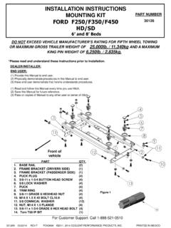
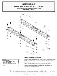
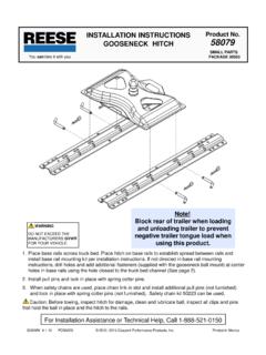
1 COVER PAGE. 30035 base rail MOUNTING KIT. 10 BOLT rail KIT. NOTE! Prior to installing product, please visit one of our websites to assure your kit contains the most recent revision to installation instruction and verify vehicle application. 2006,2007,2008,2009,2010,2011,2012,2013, 2014, 2017 Horizon Global America Inc . Made in China Cover 30035IN 1/31/2017 Rev. U. Page INSTALLATION INSTRUCTIONS. 30035 base rail MOUNTING KIT. 10 BOLT rail KIT. DEALER/INSTALLER: (1) Provide this Manual to end user. (2) Physically demonstrate procedures in this Manual to end user. (3) Have end user demonstrate that he/she understands procedures. END USER: (1) Read and follow this Manual every time you use Hitch. (2) Save this Manual for future reference. (3) Pass on copies of Manual to any other user or owner of Hitch. 14. 15. 25. 5. 3 14. 15. 10. 9. 1. 7. 6. 8. BASERAILS QTY. 4. 1. LONG BRACKET (2). 2. SHORT BRACKET (2). 3. FILLER SPACER (10). 4. SPACER (2) 2. 5. CARRIAGE BOLTS (10). 6. KNURLED BOLTS (8) Fig.
2 1. 7. 1/2 NUTS (18). 8. 1/2 LOCKWASHERS (18) 26. 9. 1/2 SERRATED WASHERS (6). 10. 1/2 FLAT WASHERS (4). 14. 4 1/2 CARRIAGE BOLT (2). 15. TUBE SPACER (2). 25. BASERAILS (2) NOTE: NOT ALL HARDWARE IS GOING TO BE USED ON ALL INSTALLATIONS. 26. PULL WIRE (4). For Installation Assistance or Technical Help, Call 1-888-521-0510. 2006,2007,2008,2009,2010,2011,2012,2013, 2014, 2017 Horizon Global America Inc . Made in China SHEET 1 0F 19 30035IN 1/31/2017 Rev. U. GENERAL INSTRUCTIONS FOR 30035 base rail INSTALLATION. TOOLS. 1/8" drill 3/4" Socket & Open End Wrench 17/32" drill 100 lb-ft Torque Wrench 1 drill (Some Dodge applications only) "C" Clamps 1. The following instructions should be used to mount the fifth wheel. Care and attention to detail will ensure a quick quality installation. Check parts against parts list to become familiar with parts in kit. (See Fig. 1). 2. Raise rear of truck high enough to allow jack stands to be placed under rear spring hanger bracket of truck. This will provide maximum room to install the fifth wheel brackets.
3 WARNING: If the truck is raised, be sure that the truck is properly blocked and restrained to prevent the truck from falling. Failure to do so may result in the truck suddenly falling, causing death or serious injury. 3. Do not install MOUNTING rails over plastic bed liners. Plastic bed liners must be cut out of the way. base rails may be installed on spray in liner. Note: Consult installer for recommended curing time. 4. Use only Horizon Global America Inc. supplied bolts, nuts, and washers to install this kit. All bolts are Grade 5 and nuts are Grade 5 unless specified otherwise. 5. Specific instructions for most commonly used vehicles are included. Each frame bracket must be bolted to the vehicle frame with two bolts, unless optional weld is used. CAUTION: These instructions are guidelines only. Actual installation is the responsibility of the installer and the owner. Always measure truck and trailer before installing hitch to be sure that there is clearance at the cab and at the bumper to allow for turns.
4 To prevent the trailer from hitting the cab with the trailer turned 90 , the center of the hitch should be at least 52" from the back of the cab when using a long bed truck. (Actual distance required will depend on trailer width and king pin location.) Short bed (Minimum 38 from back cab to axle center line) trucks require a minimum of a 13 extended pin box or a Reese SIDEWINDERTM Pinbox for regular maneuvers and 52 does not apply. DO NOT INSTALL ON OR. ATTEMPT TO TOW WITH A TRUCK HAVING LESS THAN A 6' BED WITHOUT A REESE SIDEWINDERTM PINBOX. INSTALLED ON THE TRAILER. 6. Measurements are given from Rear Edge of truck bed to rear edge of the base rail closest to the Rear Edge of truck for most vehicle applications (See Fig. 2). 7. Center hitch between fender wells and make sure rails are square. Adjust position of rails until both diagonal measurements are the same. This should allow installation of a gooseneck or other fifth wheels to these rails (See Fig. 2). CAUTION: Check for obstructions before drilling.
5 Failure to do so could result in damaged fuel or brake lines, structural members, etc. Horizon Global America Inc. does its best to communicate tow vehicle manufacturer changes; however, it is ultimately the responsibility of the installer to prevent damage due to installation. CAUTION: It is important that 17/32" drill be used for holes in chassis frame as rib neck bolts may break if too small a hole is used and neck may not grip if too large a hole is used. 8. Drill 10 holes identified in Fig. 2. (Hole location will vary for individual vehicle applications.) Drill all holes with 1/8". drill, and then temporarily position frame brackets to frame and align with pilot hole to ensure the brackets and holes in the bed align without any interference with any structure below the truck bed. If holes do not align with the brackets and rails, restart installation at step 7. Enlarge the pilot holes with a 17/32" drill. Install 1/2 carriage bolts into holes. Install 5/16 thick slotted spacer above or below bed to fill corrugations in bed floor.
6 NOTE: For Toyota 2000-2006 Tundra application, part #58197 spacer kit is required. Stack (1) 3/16 and (1) 5/16 thick slotted spacer to avoid crushing of truck bed. 2006,2007,2008,2009,2010,2011,2012,2013, 2014, 2017 Horizon Global America Inc . Made in China SHEET 2 0F 19 30035IN 1/31/2017 Rev. U. 9. Install MOUNTING brackets onto carriage bolts with the long brackets on forward bolts and short brackets on rearward (long and short brackets can be interchanged as needed). Secure bolts through MOUNTING brackets with serrated washers, lock washers, and hex nuts. Secure the other four bolts through the bed with flat washers, lock washers, and nuts. For Installation Assistance or Technical Help, Call 1-888-521-0510. 10. Drill two holes in frame for each bracket. Select the holes which will give the greatest spread between bolts. Install eight 1/2 -13x1-3/8 ribbed neck bolts, (threads pointing out), lock washers, and hex nuts. Tighten nuts until bolt heads seat. Lubrication of knurls of all rib neck bolts is recommended.
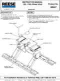
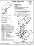
7 Note: On vehicles with heavy duty suspensions, check for interference with bolts where brackets are mounted to frame. If interference with suspension spring results, cut bolt flush to nut outboard of frame or use weld option. WARNING: DO NOT lubricate threads. It may cause bolt failure. CAUTION: Check for obstructions before drilling. Failure to do so could result in damaged fuel or brake lines, structural members, etc. Horizon Global America Inc. does its best to communicate tow vehicle manufacturer changes; however, it is ultimately the responsibility of the installer to prevent damage due to installation. 11. Torque all nuts to 85 lb-ft 12. Pull wire provided to pull rib neck bolts through frame as needed per application Drill locations will vary. See individual installation for location Note: See page 18 for a list of required adapter brackets to be used along with the universal brackets. Use side bracket/hitch base assembly to position rails (not included). Fig. 2. ROW 2. ROW 3.
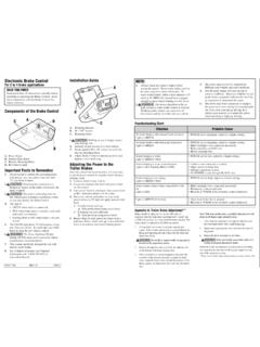
8 ROW 4. ROW 1. Front Choose 10 holes identified by black Rear Edge of of Truck Bed dots that correspond Truck with your individual configuration. ('00 to 10, GM Silverado Measure diagonal Pattern Shown) from same reference point. NOTE: Measurement Must install center bolt should be the in one of the center same. holes in each rail . Check to make sure center bolt does not Rear Edge of Truck bed to interfere with bed sill. Rear Edge of base rail 2006,2007,2008,2009,2010,2011,2012,2013, 2014, 2017 Horizon Global America Inc . Made in China SHEET 3 0F 19 30035IN 1/31/2017 Rev. U. Chevy and GM 2011 and Newer, 2500 HD & 3500 HD Silverado and Sierra CAUTION! Read pages 2-3 of these instructions before starting installation. Failure to do so could result in significant vehicle damage! IMPORTANT NOTES FOR THIS INSTALLATION: 1. Find parallel rows of bed sill spot welds in bed of truck. No drilling should be done in the ~4 between parallel rows of spot welds where the bed sill sits. ROW 4.
9 ROW 3. ROW 1. ROW 2. Rear Edge of Front of Truck Bed Vehicle 8' BOX: 29 . NOTE: For ease of 6' BOX: 25 . installation, installer can Measure from rear edge of use 13, grade 5 Hex truck bed to rear edge of head bolt and flat base rail washer. NOTE: Must install center bolt in one of the center holes in each rail . Check to make sure center bolt does not interfere with bed sill. Long Box Bed Sills King pin centered over Axle * Optional weld Short Box and some year Long Box Bed Sills pattern Side Bracket 1/4 2. 1/4 * Long bracket 1/4 2 *. 1/4 2. Drivers side of 3/4 ton HD shown Front of Vehicle Short bracket Note: Pull wires provided, will be needed to install hardware in brackets through frame. CAUTION! Check for obstructions before drilling. Failure to do so could result in damaged fuel or brake lines, structural members, etc. Horizon Global America Inc. does its best to communicate tow vehicle manufacturer changes; however, it is ultimately the responsibility of the installer to prevent damage due to installation.
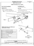
10 2006,2007,2008,2009,2010,2011,2012,2013, 2014, 2017 Horizon Global America Inc . Made in China SHEET 4 0F 19 30035IN 1/31/2017 Rev. U. GM 99 Silverado, Sierra (not Sierra Classic) models. Chevy & GM 00 and newer 1500 Silverado Sierra. 00 to 10' HD models, and '04 & up 1500 Crew Cab with 5'8 bed (Reese SidewinderTM Pinbox required for 5'8 bed). CAUTION! Read pages 2-3 of these instructions before starting installation. Failure to do so could result in significant vehicle damage! IMPORTANT NOTES FOR THIS INSTALLATION: 1. Find parallel rows of bed sill spot welds in bed of truck. No drilling should be done in the ~4 between parallel rows of spot welds where the bed sill sits. NOTE: ROW 2. ROW 1. ROW 3. ROW 4. Front of Must install center bolt in Vehicle one of the center holes in each rail . Check to make sure center bolt does not interfere with NOTE: For ease of bed sill. installation, installer can use 13, grade 5 Hex head bolt and flat washer. Rear Edge of Truck Bed 8' Box: 30.