Transcription of 30e, 40e, 50e, 60e, & 80e, fanned balanced flue gas …
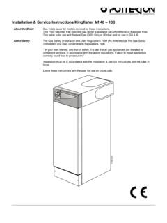
1 30e, 40e, 50e, 60e, & 80e, fanned balanced fluegas fired boilersTHIS APPLIANCE IS FOR USE WITH NATURAL GAS (G20) ONLYI nstallation and Servicing InstructionsLEAVE THESE INSTRUCTIONS ADJACENT TO THE GAS (90/396/EEC)POTTERTON PROFILE 30e No. 41 . PROFILE 40e No. 41 . PROFILE 50e No. 41 . PROFILE 60e No. 41 . PROFILE 80e No. 41 . This appliance must be installed and serviced by a competent person as stated in the Gas Safety (Installationand Use) Regulations boilers are certified for safety, it is therefore important that no external control devices ( flue dampers,economisers, etc.) be directly connected to these appliances unless covered by these installation instructions or otherwiserecommended in writing. Any direct connection of a control device not approved by Potterton could invalidate the certificateand the normal OF CONTENTS - Page 2 GeneralPage No. 2 Site RequirementsPage No. 3 Optional ExtrasPage No. 2 Technical DataPage No. 6 AccessoriesPage No.
2 3 Installation InstructionsPage No. 11 Installation DataPage No. 3 CommissioningPage No. 18 boiler DimensionsPage No. 3 Health and Safety InformationBack PageControl Systems, Pipework andWiring GuideSupplied inUser s InstructionsLiterature PackGENERAL - Page 2 Potterton Profile boilers are fully automatically controlledwall mounted fan powered balanced flue appliances, usinga cast iron heat exchanger and are available in five outputsranging from (20,000-80,000 Btu/h).The boilers which are designed to provide domestic hotwater and/or central heating must be used on INDIRECThot water systems only. The cast iron heat exchangers aresuitable for use on open vented gravity domestic hotwater/pumped central heating systems or fully pumpedsystems which may be sealed or open boilers can be supplied with either of the following typesof flue system:1)Standard horizontal flue system suitable for wallthickness of 100mm (4 in.) to 510mm (20 in.).2)2 metre horizontal flue system which provides amaximum flue length Of 1955mm (77 in.
3 3)Vertical flue system which allows the flue to passthrough a flat roof and terminate at a maximum heightof 1980mm (78 in.) measured from the top of the EXTRAS - Page 2 The following are kits available as optional extras: Internal Fitment Kit, which is suitable for a maximum wallthickness of 51 0mm (20 in.) is to be used where access tothe outside wall is Cover Kits, located on top of the boiler anddesigned to conceal the pump, and/or any motorised valvesinstalled above the boiler . (Note: Pump cannot be fittedabove the boiler if the vertical flue kit is used).Terminal Wall Plate, where necessary can be fitted to theoutside wall face to improve the appearance, after makinggood around the Guard, to be used when the terminal is fitted lessthan 2m above a balcony, above ground or above a flat roofto which people have fitting instructions are provided with each PART - Page 3 The following Potterton Myson controls are recommendedfor use with your boiler .
4 -Electronic Programmer EP2001, EP3001, or EP6000 Cylinder Thermostat PTT2 or PTT1 00 Room Thermostat PRT2 or PRT1 00 Frost Thermostat PRT1 00 FRMotorised Zone Valve M5V222 or M5V228 Motorised Diverter Valve M5V322 Thermostatic Radiator ValveData sheets describing these products are available DATA - Page 3 The installation of the boiler must be in accordance with thelatest relevant requirements of the Gas Safety (Installationand Use) Regulations, local building regulations, lEE WiringRegulations and the Byelaws of the Local recommendations are contained in the followingBritish Standards and Codes of , B55440 Part 1B55440 Part 2 B55449 Part 1B55546 B5481 4. WATER GAS PUBLICATION SAFETY (INSTALLATION AND USE) STANDARDS (SCOTLAND) DIMENSIONS - Page *NOTE:IF PIPEWORK IS TO BE RUN DOWN THE BACK OF THE BOILERTHE NORMAL CLEARANCE OF 25mm BETWEEN THE REAR OFTHE boiler AND WALL CAN BE INCREASED TO 35mm IFDESIRED BY INVERTING THE boiler MOUNTING PLATE DURINGINSTALLATION(Dimensions in brackets apply when the mounting plate is inverted).
5 SITE REQUIREMENTS - Page 3 These boilers are not suitable for external installation andshould not be fitted directly above a cooking appliance. Theboiler may be installed in any room, although particularattention is drawn to the requirements of the current Regulations and in Scotland, the electrical provisionsof the Building Standards applicable in Scotland withrespect to theinstallation of the appliance in a room containing a bath a room-sealed appliance is installed in a roomcontaining a bath or shower, any electrical switch orappliance control, utilising mains electricity should be sosituated that it cannot be touched by a person using thebath or REQUIREMENTS - Page 4 FIG. 2 GENERAL ARRANGEMENTSITE REQUIREMENTS - Page 5 Where the installation of the boiler will be in an unusuallocation, special procedures may be necessary and BS 6798gives detailed guidance on this that the gas supply pipe and meter are large enoughfor this appliance and any others that may be run off thesame meter.
6 Reference should be made to B56891 boiler Mounting SurfaceThe boiler must be mounted on a flat wall, which may be ofcombustible material and must be sufficiently robust to takethe weight of the boiler . The requirements of the localauthorities and the Building Regulations must be adhered NOTICE:TIMBER FRAMED HOUSESIf the appliance is to be fitted in a timber framed building, itshould be fitted in accordance with British Gas Publication Operational Procedures for Customer Service Part 19. If inany doubt, advice should be sought from the local region ofBritish Around the BoilerThe following minimum clearances must be maintained afterinstallation, for correct operation and servicing of the boiler :610mm (2 ft) at the front of the boiler5mm ( in) each side of the boiler50mm (2 in) at the top (measured from the top of the boilercase), except where the optional extra pump cover is to befitted, when 178mm (7 in) should be (4 in) at the bottom of the clearances to these are required duringinstallation for lifting the boiler and 127mm (5 in) is requiredat the top of the boiler for access to the pipe the boiler is to be installed in a confined space such as acupboard, the space will need ventilating.
7 Openings must beprovided at the top and bottom of the Cupboard each ofwhich should have a free area as shown in TABLE 1. Furtherdetails for installation of a boiler within a compartment aregiven in BS 1 AIR VENT AREASPROFILEin2cm230e1610340e2113550e261 7060e3220680e43277If the openings draw air from outside the building the freeareas may be halved. Refer to BS 5440 Part 2 for Flue Terminal and DuctingThe fresh air inlet and flue ducts can be run from either theleft, right, rear or top of the boiler to a miniature terminal onthe outside of the minimum spacings from the terminal to obstructions andventilation openings are shown in FIG. 3. For informationappertaining to horizontal flue lengths reference should bemade to FIG. a terminal is fitted less than 2m above a balcony, aboveground or above a flat roof to which people have accessthen a suitable terminal guard should be fitted. ( ).Refer to B55440 Part 1 for further 3 THE SITING OF BALANCEDFLUE TERMINALSINFORMATION RELATING TO VERTICAL FLUING ISPROVIDED IN THE PACK CONTAINING THE VERTI-CALFLUE a flue terminal is fitted less than 1000mm from aplastic or painted gutter or 500mm from painted eaves, analuminium shield of 1000mm length should be fitted tounderside of gutter or car port or other add-on extension should consist of aroof or a roof and one other wall.
8 If it consists of a roof andtwo other walls the installation shall be treated as suspectand further advice BELOW AN OPENABLEWINDOW, AIR VENT, OR ANY OTHERVENTILATION GUTTER, DRAIN/SOIL A BALCOY OR CAR PORT VERTICAL DRAIN PIPES ANDSOIL INTERNAL OR EXTERNAL ADJACENT GROUND OR A SURFACE FACING THE TERMINALS1, OPENING (DOOR/WINDOW) INCARPORT INTO DWELLING1, FROM A TERMINAL ONTHE SAME WALL1, FROM A TERMINAL ONTHE SAME TO OPENING150 SITE REQUIREMENTS - Page 6 ALL MODELS REAR OR SIDE FLUEINGFIG. 4 FLUE LENGTHS MAXIMUM LENGTH X STANDARD FLUE SYSTEM510mm(20in) 1 METRE FLUE SYSTEM955mm(37in)ELECTRICITY SUPPLYA 240 volts -~ 50Hz, single phase electricity supply fused to3 amperes, must be provided in accordance with the latestedition of the Wiring Regulations and any other localregulations that may apply. The current rating of the wiringto the boiler must exceed 3 amperes and have a crosssectional area of at least in accordance withB56500 Table supply to the boiler and its associated equipment shouldbe controlled by an exclusive 3A fused double pole switch(having at least 3mm contact separation in both poles) so thatcomplete isolation from the supply can be achieved to enableservicing work to be carried out in DATAM aximum working (100 ft)Gas supply connectionRc.
9 1/2 (i/2in BSPM inimum working head onFemale)Fully Pumped systems305mm (1 ft)Minimum circulating headWater ContentModels 30e, 40eon Gravity (4ft) litre ( gal)Gas supply pressure20mbarModels 50e, 60e &Maximum Flow temperature820C80eElectricity supply240v~-50Hz litre ( gal)at 3 APower consumption80 wattsAppliance Weight-installedModels 30e, 40e(excluding pump)Appliance Weight-lift52kg (115 Ibs)Flow/Return connection22mm copper on46kg (101 Ibs)30e, 40e models28mm copper onAppliance Weight-installedModels 50e, 60e &50e, 60e, 80eAppliance Weight-lift80emodels62kg (137 Ibs)53kg (117 Ibs)SITE REQUIREMENTS - Page 7 BOILERINJECTORGAS RATEINPUTOUTPUTBURNER PRESSURESIZESIZEm3/h (ft3/h)kW(Btu/h)kW(Btu/h)mbarin ( ) (26702) (20000) ( ) (33068) (25000) ( ) (38217) (30000) ( ) (39682) (30000) ( ) (45336) (35000) ( ) (50955) (40000) ( ) (52000) (40000) ( ) (57692) (45000) ( ) (64000) (50000) ( ) (65300) (50000) ( ) (70950) (55000) ( ) (77000) (60000) ( ) (79800) (60000) ( ) (91503) (70000) ( ) (103200) (80000) PUMP SELECTIONThe resistance through the heat exchanger when operatingwith a water flow rate producing an 11 0C temperature riseat maximum boiler output are shown in TABLE 2.
10 If othercontrols, such as three-position valves are used in thesystem, the resistance through them, quoted in theirmanufacturer s literature must be taken into account. Thepump may be fitted on either the flow or return and MUSTbe wired directly to the boiler terminal block, see FIG. 24. Itmust be fitted with two isolating valves which are positionedas close to the pump as possible. Closing of any valve mustalways leave the open vent 2 FIG. 5 PRESSURE LOSS ACROSS BOILERSITE REQUIREMENTS - Page 8 The SystemThe boiler must be used on INDIRECT hot water systems only. It issuitable for use on open vented gravity domestic hot water/pumpedcentral heating systems or, fully pumped systems which may besealed or open system should be designed so that the maximum static headdoes not exceed m (100 ft) and a minimum on fully pumpedsystems of 305 mm (1 ft). See FIG. domestic hot water circuits should have a minimumcirculating head of m (4ft). See FIG. ensure optimum boiler performance on both gravity hot waterand fully pumped systems a change-over switch is incorporated inthe boiler control box.
