Transcription of 36 PORTAL FRAMES - steel-insdag.org
1 PORTAL FRAMES Version II 36 - 1 PORTAL FRAMES INTRODUCTION The basic structural form of PORTAL FRAMES was developed during the Second World War, driven by the need to achieve the low - cost building envelope. Now they are the most commonly used structural forms for single-storey industrial structures. They are constructed mainly using hot-rolled sections, supporting the roofing and side cladding via cold - formed purlins and sheeting rails. With a better understanding of the structural behaviour of slender plate elements under combined bending moment, axial load and shear force, many fabricators now offer a structural frame fabricated from plate elements.
2 These FRAMES are composed of tapered stanchions and rafters in order to provide an economic structural solution for single-storey buildings. PORTAL FRAMES of lattice members made of angles or tubes are also common, especially in the case of longer spans. The slopes of rafters in the gable PORTAL FRAMES ( ) vary in the range of 1 in 10 to 1 in 3 depending upon the type of sheeting and its seam impermeability. With the advent of new cladding systems, it is possible to achieve roof slopes as low as 10. But in such cases, frame deflections must be carefully controlled and the large horizontal thrusts that occur at the base should be accounted for.
3 Generally, the centre-to-centre distance between FRAMES is of the order 6 to m, with eaves height ranging from 6 -15 m. Normally, larger spacing of FRAMES is used in the case of taller buildings, from the point of economy. Moment-resisting connections are to be provided at the eaves and crown to resist lateral and gravity loadings. The stanchion bases may behave as either pinned or fixed, depending upon rotational restraint provided by the foundation and the connection detail between the stanchion and foundations. The foundation restraint depends on the type of foundation and modulus of the sub-grade. FRAMES with pinned bases are heavier than those having fixity at the bases.
4 However, FRAMES with fixed base may require a more expensive foundation. For the design of PORTAL FRAMES , plastic methods of analysis are mainly used, which allows the engineer to analyse FRAMES easily and design it economically. The basis of the plastic analysis method is the need to determine the load that can be applied to the frame so that the failure of the frame occurs as a mechanism by the formation of a number of plastic hinges within the frame . The various methods of plastic analysis are discussed in an earlier chapter. In describing the plastic methods of structural analysis, certain assumptions were made with regard to the effect of axial force, shear, buckling etc.
5 Unless attention is given to such factors, the frame may fail prematurely due to local, or stanchion or rafter buckling, prior to plastic collapse. Copyright reserved 36 PORTAL FRAMES Version II 36 - 2In the analysis, the problem is to find the ultimate load of a given structure with known plastic moment values of its members. But in design, the problem is reversed. Given a certain set of loads, the problem is to select suitable members. HAUNCHED PORTAL FRAMES The most common form of PORTAL frame used in the construction industry is the pinned-base frame with different rafter and column member size and with haunches at both the eaves and apex connections ( ).
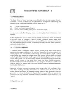
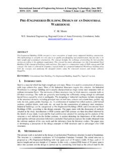
6 These two important design features of the modern PORTAL frame have been developed over a number of years, from practical and economic considerations. Due to transportation requirements, field joints are introduced at suitable positions. As a result, connections are usually located at positions of high moment, at the interface of the column and rafter members (at the eaves) and also between the rafter members at the apex (ridge) (See ). It is very difficult to develop sufficient moment capacity at these connections by providing 'tension' bolts located solely within the small depth of the Fig. 1 Typical gable frame a b (b) Eaves detail connections (a) Haunched PORTAL frame ridge eaves rafter stanchion PORTAL FRAMES Version II 36 - 3rafter section .
7 Therefore the lever arm of the bolt group is usually increased by haunching the rafter members at the joints. This addition increases the section strength. Although a short length of the haunch is enough to produce an adequate lever arm for the bolt group, haunch is usually extended along the rafter and column adequately to reduce the maximum moments in the uniform portion of the rafter and columns and hence reduce the size of these members. But due to this there will be a corresponding increase in the moment in the column and at the column-haunch-rafter interface. This allows the use of smaller rafter member compared to column member. The resulting solution usually proves to be economical, because the total length of the rafter is usually greater than the total length of the column members.
8 The saving in weight is usually sufficient to offset the additional cost of haunch. The haunched frame may be designed in a manner similar to that of an unhaunched frame , the only difference being that the hinges, which were assumed to be at nodes, are forced away from the actual column-rafter junction to the ends of the haunches. Provided the haunch regions remain elastic, hinges can develop at their ends. The haunch must be capable of resisting the bending moment, axial thrust and shear force transferred by the joining members. The common practice is to make the haunch at the connection interface approximately twice the depth of the basic rafter section , so that the haunch may be fabricated from the same basic section .
9 GENERAL DESIGN PROCEDURE The steps in the plastic design of portals, according to SP: 6(6) 1972, are given below: a) Determine possible loading conditions. b) Compute the factored design load combination(s). c) Estimate the plastic mo ment ratios of frame members. d) Analyse the frame for each loading condition and calculate the maximum required plastic moment capacity, Mp e) Select the section , and f) Check the design according to new IS: 800. The design commences with determination of possible loading conditions, in which decisions such as, whether to treat the distributed loads as such or to consider them as equivalent concentrated loads, are to be made.
10 It is often convenient to deal with equivalent concentrated loads in computer aided and plastic analysis methods. In step (b), the loads determined in (a) are multiplied by the appropriate load factors to assure the needed margin of safety. This load factor is selected in such a way that the real factor of safety for any structure is at least as great as that decided upon by the designer. The load factors to be used for various load combinations are presented in an earlier chapter on Limit states method. The step (c) is to make an assumption regarding the ratio of the plastic moment capacities of the column and rafter, the frame members. Optimum plastic design methods present a PORTAL FRAMES Version II 36 - 4direct way of arriving at these ratios, so as to obtain an optimum value of this ratio.