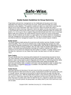
Transcription of 39523 Select II - BrakeBuddy
1 Inventor and Leader in Portable Technology!Hopkins Manufacturing Corporation | 428 Peyton St. Emporia, KS 66801 | Read all instructions before installing or operating the Select II .Failure to understand how to install or operate Select II could result in property damage, personal injury or HELP? CALL - 1-800-470-2287(MONDAY - FRIDAY 8AM - 5PM CST) Select II Portable Braking SystemHopkins Manufacturing Corporation 1-800-470-2287 Dash Mount ConnectorTowed vehicle firewallGrommetGround15 AMPbattery chargerGround wireto vehicle frameBattery wirePositive battery terminalBlack wire from Dash Mountto battery wireConnect brown and red wiresfrom Dash Mount Connectorto wires from Break-Away SwitchConnect to RVauxiliary powerBreak-Away Switch8 feet of wire8 feet of wire4 feet of wire4 feet of wireINSIDE THE BOXBRAKEBUDDY UNDER TOWED VEHICLE HOOD WIRINGPLEASE FOLLOW THIS DIAGRAM TO INSTALL BrakeBuddy AND GET READY TO TOWNOTE.
2 If there is ANY shipping damage, immediately call BrakeBuddy Technical Service at 800-470-2287 PRIOR TO THE SET-UP OF BrakeBuddy Select II , REMOVE ALL CONTENTS FROM THE SHIPPING Lock ReleaseEasy-Pull Power CordBreak-Away Kit15 AMP ChargerWireless RemoteDash Mount ConnectorSelect II UnitQuick Connect ClevisHopkins Manufacturing Corporation 1-800-470-2287 1. Look under dash in towed vehicle driver side for grommets or holes to come through the firewall. 2. Drill a hole wide enough to route the wiring from the Dash Mount Connector through the firewall to the Select mounting location for Dash Mount Connector and route wire from inside of vehicle through firewall into the engine compartment. Use provided grommet to protect Use 2 screws, 2 washers and 2 nuts to secure Dash Mount Connector to vehicle BREAK-AWAY IS AN IMPORTANT PART OF THE BrakeBuddy SYSTEM AND IS REQUIRED BY LAW IN MOST STATES.
3 DO NOT OPERATE YOUR BrakeBuddy WITHOUT A PROPERLY FUNCTIONING JUNCTION BOX1. Find a convenient, sturdy place on the front of your towed vehicle to mount the junction box (B). This should be installed on the driver s side of the vehicle if Clean the mounting surface and attach the Velcro patch (A) (Fig. 1)3. Attach the junction box (B) to the velcro patch (A) so the pin with the ring faces forward and the wiring harness feeds back into the engine Place the mounting bracket (C) over the junction box (B) and mark the hole locations to be drilled and Remove bracket (C) and junction box (B). Drill marked holes with a 1/8 metal drill Replace the junction box (B) and attach the bracket (C) using hex socket head capscrews (D) or sheet metal screws (E) provided (Fig.)
4 2).INSTALL DASH MOUNT CONNECTORBREAK-AWAY INSTALLATIONNOTE: Please do not drill before making sure there is nothing behind the firewall that may cause damage to your : For thin sheet metal or plastic, it may be necessary to reinforce the plastic or thin metal to ensure bracket will not separate from the vehicle when the break-away pin is pulled. If you are going to drill through thicker metal, use hex socket head capscrews (D). You will need to drill a hole using a #25 drill bit and tap the hole using a 10-24 2 FIG. 1 ABCDEH opkins Manufacturing Corporation 1-800-470-2287 After attaching your towed vehicle to your coach and all hook-ups are complete, you will need to attach the break-away cable from the junction box to the motorhome.
5 DO NOT ATTACH OR WRAP THE CABLE AROUND THE TOW BAR, HITCH OR Attach the small clip on the cable to the loop on the pull pin of the junction box, and then attach the large clip to the motorhome. The coiled break-away cable fits all applications and needs no Install the BrakeBuddy in your towed vehicle 3. Before the start of every trip, pull the break-away pin to test that the break-away system activates the BrakeBuddy .4. When the use of the towed vehicle is needed, simply unhook the small clip from the loop on the pull pin of the junction box. Unplug the power cord from the BrakeBuddy and the dash mount. Store power cord with BrakeBuddy .1. Lift lever on back of unit to pull handle up into ready Insert Grey end of power cord into front of Attach the lock nut and clevis assembly to the arm Place BrakeBuddy in floor of drivers side towed vehicle.
6 5. Attach clevis to brake Move BrakeBuddy forward until the arm extension is fully retracted. Make sure the vehicle s brake pedal is not being Adjust the drivers seat forward until it is less than a quarter inch away from the BrakeBuddy handle. Again, make sure the vehicles brake pedal is not being Plug in Black end of the power cord into Dash Mount With vehicle s engine OFF, push the red Auto Start Button located on top of the BrakeBuddy . The arm will automatically extend / cycle 5 times. This will remove any vacuum stored in the brake vacuum reservoir of the towed vehicle as well as diagnose any errors in the system THE BREAK-AWAY SYSTEMSET UPStep to raise handleStep power cordREADY POSITIONThis is how the unit should look prior to placing in floor of towed vehicleHopkins Manufacturing Corporation 1-800-470-2287 Adjust the air pressure to match the weight of your towed vehicle.
7 The braking pressure, or how hard your towed vehicle will brake in tow, is adjusted by the + / - Buttons (A) located on top of the BrakeBuddy . To find the correct pressure setting specific for your towed vehicle, please refer to the Vehicle Weight Formula chart below. The display will adjust in increments or decrements of 5 when held down and displays air pressure from 10 to 75 PSI. After 5 minutes the display will power down. Upon a button press, the display will power on. Choose your braking technology Braking Technology fully employs the brakes when activated, taking the entire weight of the towed vehicle off of the motorhome Braking Technology, when activated, performs the same braking force in the towed vehicle that is performed in the :Install the AA battery (included) into the wireless remote system.
8 Attach nonskid pad to the back of the remote system. Place remote and nonskid pad on a suitable semi-flat surface. The nonskid pad will secure the remote system. If you wish to change the braking technology preference, press the Braking Mode Button (C) to Select full or proportional braking. The braking preference can be changed while the Sensitivity either on the remote or on top of the main unit. The sensitivity is how hard you must apply the brakes in the motorhome before the BrakeBuddy will engage the in your towed vehicle. The more lights that are illuminated, the easier the BrakeBuddy will activate. Each time BrakeBuddy is installed, the sensitivity setting remains in the last used setting. Start at setting #4 and adjust your preferred setting as you are driving (using the remote).
9 For Hybrid Vehicles: At 20 PSI hybrid light will come on. Adjust lower if needed based on the amount of braking force preferred. (B)UNIT OPERATION INSTRUCTIONSBCADIAGNOSTIC FEATURESVEHICLE WEIGHT FORMULASYSTEM NORMAL Everything is working properlyLOW BATTERY Battery voltage has dropped below 10 volts. Recharge towed vehicle battery before travelingERROR - Call 1-800-470-2287 BLEED BRAKES Depress Auto Start ButtonHYBRID Mode for vehicles with electric power assist brakes1,500 - 2,000700 - 90025352,000 - 2,500900 - 1,15035452,500 - 3,0001,150 - 1,40040503,000 - 3,5001,400 - 1,60045553,500 - 4,0001,600 - 1,80050604,000 - 4,5001,800 - 2,0501999+ Jeep Gr. Cherokee55654,500 - 5,0002,050 - 2,30065755,000 +2,300 +7575 Hopkins Manufacturing Corporation 1-800-470-2287 The BrakeBuddy Remote provides 2-way communication from the motorhome to the towed vehicle and provides visual indications of problems that are occurring.
10 (Fig. 3)F - Main Unit Error (red light will activate) Stop and check the main unit diagnostics for - Battery Low on Remote (replace with new AA battery)H - Breakaway Warning (red light and audible signal will activate) Stop Immediately!I - On / Off SwitchA 12-volt DC power cord is also included. This bypasses the on/off switch, and battery removal when using the 12-volt DC cord is not SYNCHRONIZE PROCEDURE:This device works similarly to a universal garage door opener. If this remote ever becomes un-synced with the main unit, simply perform the following procedure:1. Power up / turn on both devices (dinghy and remote).2. On the BrakeBuddy unit, hold down the (+) and (_) buttons (A) simultaneously until the Air Pressure setting reads LL (Fig.)