Transcription of 4.10 Elevators. General Automatic Operation. Hall …
1 UAccessibility Guidelines for Buildings and Facilities Elevators. General . Accessible elevators shall be on an accessible route and shall comply with and with the ASME , Safety Code for Elevators and Escalators. Freight elevators shall not be considered as meeting the requirements of this section unless the only elevators provided are used as combination passenger and freight elevators for the public and employees. Automatic Operation. elevator operation shall be Automatic . Each car shall be equipped with a self-leveling feature that will automatically bring the car to floor landings within a tolerance of 1/2 in (13 mm) under rated loading to zero loading conditions.
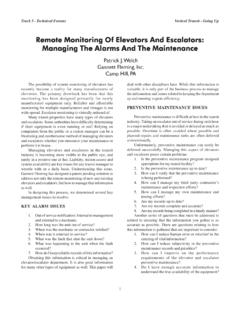
2 This self-leveling feature shall be Automatic and independent of the operating device and shall correct the overtravel or undertravel. hall Call Buttons. Call buttons in elevator lobbies and halls shall be centered at 42 in (1065 mm) above the floor. Such call buttons shall have visual signals to indicate when each call is registered and when each call is answered. Call buttons shall be a minimum of 3/4 in (19 mm) in the smallest dimension. The button designating the up direction shall be on top. (TUSee Fig. 20UT.) Buttons shall be raised or flush. Objects mounted beneath hall call buttons shall not project into the elevator lobby more than 4 in (100 mm).
3 hall Lanterns. A visible and audible signal shall be provided at each hoistway entrance to indicate which car is answering a call. Audible signals shall sound once for the up direction and twice for the down direction or shall have verbal annunciators that say "up" or "down." Visible signals shall have the following features: (1) hall lantern fixtures shall be mounted so that their centerline is at least 72 in (1830 mm) above the lobby floor. (TUSee Fig. 20UT.) (2) Visual elements shall be at least 2-1/2 in (64 mm) in the smallest dimension. (3) Signals shall be visible from the vicinity of the hall call button (TUsee Fig. 20UT). In-car lanterns located in cars, visible from the vicinity of hall call buttons, and conforming to the above requirements, shall be acceptable.
4 Raised and Braille Characters on Hoistway Entrances. All elevator hoistway entrances shall have raised and Braille floor designations provided on both jambs. The centerline of the characters shall be 60 in (1525 mm) above finish floor. Such characters shall be 2 in (50 mm) high and shall comply with Permanently applied plates are acceptable if they are permanently fixed to the jambs. (TUSee Fig. 20UT). Figure 20 Hoistway and elevator Entrances NOTE: The Automatic door reopening device is activated if an object passes through either line A or line B. Line A and line B represent the vertical locations of the door reopening device not requiring contact.
5 * Door Protective and Reopening Device. elevator doors shall open and close automatically. They shall be provided with a reopening device that will stop and reopen a car door and hoistway door automatically if the door becomes obstructed by an object or person. The device shall be capable of completing these operations without requiring contact for an obstruction passing through the opening at heights of 5 in and 29 in (125 mm and 735 mm) above finish floor (TUsee Fig. 20UT). Door reopening devices shall remain effective for at least 20 seconds. After such an interval, doors may close in accordance with the requirements of ASME * Door and Signal Timing for hall Calls.
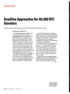
6 The minimum acceptable time from notification that a car is answering a call until the doors of that car start to close shall be calculated from the following equation: T = D/( ft/s) or T = D/(445 mm/s) where T total time in seconds and D distance (in feet or millimeters) from a point in the lobby or corridor 60 in (1525 mm) directly in front of the farthest call button controlling that car to the centerline of its hoistway door (TUsee Fig. 21)UT. For cars with in-car lanterns, T begins when the lantern is visible from the vicinity of hall call buttons and an audible signal is sounded. The minimum acceptable notification time shall be 5 seconds.
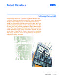
7 Figure 21 Graph of Timing Equation Door Delay for Car Calls. The minimum time for elevator doors to remain fully open in response to a car call shall be 3 seconds. Floor Plan of elevator Cars. The floor area of elevator cars shall provide space for wheelchair users to enter the car, maneuver within reach of controls, and exit from the car. Acceptable door opening and inside dimensions shall be as shown in TUFig. 22UT. The clearance between the car platform sill and the edge of any hoistway landing shall be no greater than 1-1/4 in (32 mm). Figure 22 Minimum Dimensions of elevator Cars Diagram (a) illustrates an elevator with a door providing a 36 inch (915 mm) minimum clear width, in the middle of the elevator .
8 The width of the elevator car is a minimum of 80 inches (2030 mm). The depth of the elevator car measured from the back wall to the elevator door is a minimum of 54 inches (1370 mm). The depth of the elevator car measured from the back wall to the control panel is a minimum of 51 inches (1291 mm). Diagram (b) illustrates an elevator with door providing a minimum 36 inch (915 mm) clear width, located to one side of the elevator . The width of the elevator car is a minimum of 68 inches (1730 mm). The depth of the elevator car measured from the back wall to the elevator door is a minimum of 54 inches (1370 mm). The depth of the elevator car measured from the back wall to the control panel is a minimum of 51 inches (1291).
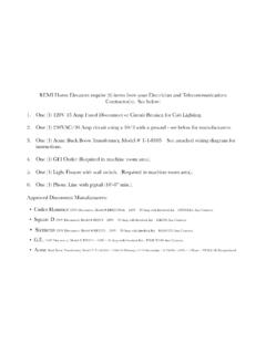
9 Floor Surfaces. Floor surfaces shall comply with Illumination Levels. The level of illumination at the car controls, platform, and car threshold and landing sill shall be at least 5 footcandles ( lux). * Car Controls. elevator control panels shall have the following features: (1) Buttons. All control buttons shall be at least 3/4 in (19 mm) in their smallest dimension. They shall be raised or flush. (2) Tactile, Braille, and Visual Control Indicators. All control buttons shall be designated by Braille and by raised standard alphabet characters for letters, arabic characters for numerals, or standard symbols as shown in TUFig. 23(a)UT, and as required in ASME Raised and Braille characters and symbols shall comply with The call button for the main entry floor shall be designated by a raised star at the left of the floor designation TU(see Fig.)
10 23(a)UT). All raised designations for control buttons shall be placed immediately to the left of the button to which they apply. Applied plates, permanently attached, are an acceptable means to provide raised control designations. Floor buttons shall be provided with visual indicators to show when each call is registered. The visual indicators shall be extinguished when each call is answered. (3) Height. All floor buttons shall be no higher than 54 in (1370 mm) above the finish floor for side approach and 48 in (1220 mm) for front approach. Emergency controls, including the emergency alarm and emergency stop, shall be grouped at the bottom of the panel and shall have their centerlines no less than 35 in (890 mm) above the finish floor (TUsee Fig.