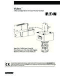
Transcription of 4/2 and 4/3 proportional directional valves, H/A/D …
1 1/18RA 29 061 and 4/3 proportional directional valves, directly controlled, with electricalposition feedbackModels 4 WRE and 4 WREEN ominal sizes 6 and 10 Series 2 XMaximum operating pressure 4600 PSI (315 bar)Maximum flow GPM (240 L/min) H/A/D 5881/97 FeaturesH/A/D 5732/97 DescriptionPageFeatures1 Ordering details2 Symbols2 Function, section3 Technical data4 and 5 Electrical connections, plug-in connector5 Integrated valve electronics for model 4 WREE6 and 7plug-in connector, plug allocation,block circuit diagram / connection allocationCharacteristic curves8 to 14 Unit dimensions15 and 16 External control electronics for model 4 WRE17 and 18 Model 4 WRE 6 ..-2X/G24K4/V with plug-in connectors andassociated control electronics (separate order)Model 4 WREE 10.
2 -2X/G24K31/..Vwith integrated control electronics Directly controlled proportional valve for the control of directionand magnitude of a flow Actuation is by proportional solenoids with central thread andremovable coil Electrical position feed-back For subplates:porting pattern to DIN 24 340 form A, ISO 4401, CETOP-RP 121 H,NFPA R1, and ANSI D 03, D 05 Subplates to catalog sheets RA 45 052 and RA 45 054(separate order), see pages 15 and 16 Spring centered control spool Model 4 WREE, integrated valve electronics with interface A1and F1 Control electronics for model 4 WRE: electronic amplifierVT-VRPA2-1-1X in Eurocard format (separate order)RA 29 061 : 29 061 Hydraulics2/184 WRE / 4 WREEa0bABPTabPTABa0babPABT0baa0bABPTabAB a0bPTabABPTb0baABPTb0baABPTa0baABPTa0ba4 WRE 2X / G24/V*Further detailsin clear textV =FPM rectangular rings,suitable for mineral oil(HL, HLP) to DIN 51 524 For WREE:A1 =command value input 10 VDCF1 =command value input 4 to 20 mAElectrical connection for WREK4 =with component plug DIN 43 650-AM2without plug-in connector(solenoid, position transducer)plug-in connector separate ordersee page 5 Electrical connection for WREEK31 = with component plug to E DIN 43 563-AM6-3without plug-in connectorplug-in connector separate ordersee page 6G24 =Power supply voltage 24 VDC2X =Series 20 to 29(20 to 29.)
3 Unchanged installation and connection dimensions)Nominal flows at a valve pressure differential Dp = 145 PSI (10 bar)Size 608 = GPM (8 L/min)16 = GPM (16 L/min)32 = GPM (32 L/min)Size 1025 = GPM (25 L/min)50 = GPM (50 L/min)75 = GPM (75 L/min)Ordering detailsWithout integratedcontrol electronics= No codeWith integrated controlelectronics (standard electronics)= ENominal size 6= 6 Nominal size 10= 10 SymbolsWith symbols E1-, V1- and W1-:P A: qV maxB T: qV/2P B: qV/2A T: qV maxWith sysmbols E3- and W3-:P A: qV maxB T: closedP B: qV/2A T: qV maxNote:For spools W, WA and WB there is in the neutral positiona connection between A and T and B to T with % of the relevant nominal EB= WB= EE1-= E3-= W W1-= W3-= EA= WA=VV1-Model / 4 WREE3/18 Rexroth HydraulicsRA 29 061 "a""b"7531246108(P)BAT9AB"a""b"753124610 8(P)BAT8911 Function, sectionModel with 2 switching positions:(models or )The function of this valve version is basically the same as that of the valvewith 3 switching positions.
4 The 2 switching position valves are however onlyfitted with solenoid "a" (5) or solenoid"b" (6) . A plug (10) is fitted in placeof the 2nd proportional 4/2 and 4/3 proportional directional valves are directly controlledcomponents of subplate mounting design. They are actuated byproportional solenoids with central thread and removable coil. Thesolenoids are controlled by either external control electronics (modelWRE) or by the integrated valve electronics (model WREE).Design:The valve basically consists of: Housing (1) with mounting face Control spool (2) with compression springs (3 and 4) Solenoids (5 and 6) with central thread position transducer (7) Integrated valve electronics (8) Via the the mechanical zero point adjustment (9) isaccessable and the electrical zero point is accessable via thePg7(11) (Model 4 WREE)Functional description.
5 With de-energized solenoids (5 and 6), the control spool (2) isheld in the central position by the compression springs (3 and 4) Direct actuation of the control spool (2) by energizing one of theproportional solenoids, control of solenoid "b" (6) Movement of the control spool (2) to the left in proportion tothe electrical input signal Connection from P to A and B to T via orifice like cross-sectionswith progressive flow characteristics De-energizing of solenoids (6) The control spool (2) is returned to the central position via thecompression spring (3)In the de-energized condition the spool (2) is held in a mechanical centralposition by the solenoid return springs. The spring center position with theV-spool may not correspond to the electrical for model :Draining of the tank line is to be prevented.
6 Taking the installation conditionsinto account a back pressure valve is to be fitted (back pressure PSI (2 bar).RA 29 061 Hydraulics4/184 WRE / 4 WREET echnical data (for applications outside these parameters, please consult us!)GeneralSize 6 Size 10 Installationoptional, preferably horizontalAmbient4 WRE F ( C) 4 to + 158 ( 20 to + 70)temperature range4 WREE F ( C) 4 to + 122 ( 20 to + 50)Storage temperature range F ( C) 4 to + 176 ( 20 to + 80)Weight4 WRElbs (kg) ( ) ( )4 WREElbs (kg) ( ) ( )Hydraulic measured at = 208 SUS (46 mm2/s) and t = 104 F (40 C)Operating pressurePorts A, B, PPSI (bar)up to 4600 (315)Ports TPSI (bar)up to 3046 (210)Nominal flow qV nom at p = 145 PSI (10 bar)GPM (L/min) (8) (25) (16) (50) (32) (75)Flow, max.)
7 PermissibleGPM (L/min) (80) (180)Pressure fluidMineral oil (HL, HLP) to DIN 51 524,further fluids on requestDegree of contaminationMaximum permissible degree of contamination of the fluid toNAS 1638 class 9. We, therefore, recommend a filter with aminimum retention rate of x 75, x = temperature range F ( C) 4 to + 176 ( 20 to + 80), preferably + 104 to + 122 (+ 40 to + 50)Viscosity rangeSUS (mm2/s)97 to 1760 (20 to 380), preferably 141 to 208 (30 to 46)Hysteresis% error% sensitivity% (solenoid)Insulation to DIN 40 050exceeds NEMA class B (IP 65)Voltage modelDCSignal modelanalogCommand value signalVoltage input "A1"V 10 Current input "F1"mA4 to 20 Max. current per coilCold value at 20 C 2resistanceMax. warm value 3 Duty%100 Coil temeprature F ( C)up to 302 (150)Electrical (inductive position transducer)Electrcial measuring systeminductiveElectrical connectionplug-in connector 4-pin + Pg7-G4W1 FProtection to DIN 40 050IP 654 WRE / 4 WREE5/18 Rexroth HydraulicsRA 29 061 (16) (23) (37) ( ) (15) (30) ( ) (30) (36) (53) ( ) ( )PE12PE12PE12PE12 Technical data (for applications outside these parameters, please consult us!)
8 Note:For details regarding the environmental simulation test covering EMV (electro-magnetic compatability), climate and mechanical loadingsee RA 29 061-U (declaration regrading environmental compatibility).Electrical connection, plug-in connectorFor model 4 WRE (without integrated electronics)Plug-in connector to DIN 43 650-AF2 Solenoid a, grey, Pg11 (Z4)part no. RR00 074 683 Solenoid b, black, Pg11 (Z4)part no. RR00 074 684 Solenoid b, red-brown, 1/2 NPT (Z45)part no. RR00 004 823 Solenoid b, black, 1/2 NPT (Z45)part no. RR00 011 039 Inductive position transducerCoil connectionsPlug-in connector 4-pin Pg7-G4W1 Fpart no. RR00 023 126 Connection cable:Recommendation: up to 160 ft (50 m) cable lengthstranded 24 AWG (LiYCY 4 x mm2) with connect shield to earth ground PE on the supply diameter to in ( to mm)Electrical (integrated electronics)Supply voltageNominal voltageVDC244 WREEL ower limiting valueV19 Upper limiting valueV35 Amplifier currentA3 Input impedanceVoltage input A1 30K or higherCurrent input F1 100 Zero displacement%/10 PSI (100 bar) (control electronics)4 WREmodel VT-VRPA2-1-1 XAmplifier in Eurocard format (separate order)
9 See pages 17 and 18 or catalog sheet RA 30 1254 WREE integrated into the valve, see pages 6 and 7To amplifierSignal groundSupply groundSupplySignalConnections on the plug connectorConnections on theplug-in connectorTo amplifierTo amplifierConnections on thecomponent plugRA 29 061 Hydraulics6/184 WRE / 4 WREEABCDEF ( ) (91) ( ) (seal)ContactSignalSupply voltageA24 VDC = ( V to 35 V); Imax=2AB0 VRef. potential actual valueC0 V reference contact FDifferential amplifier inputD 10 V, Re>50k ; or mA, Re> 100 ; command valueE0 V referenceMeas. output (actual value)F 10 V (limiting load 5 mA); or mA, max. load impedance 300 ; actual valuePEconnected with heat sink and valve housingComponent plug allocationPlug-in connectorPlug-in connector to E DIN 43 563-BF6-3/Pg11 Separate order under part no.
10 RR00 021 267(plastic)For pin allocation see block circuit diagram on page 7 Integrated valve electronics for model 4 WREEA ctual value:Positive actual value (or 12 to 20 mA) at F and reference potential at C results in a flow from P to value:Positive command value (or 12 to 20 mA) at D and reference potential at E results in a flow from P to A and B to command value (or 4 to 12 mA) at D and reference potential at E results in a flow from P to B and A to a value with 1 solenoid on side a ( spool variant EA and WA) a positive command value (or 4 .. 20 mA)at D and reference potential at E results in a flow from P to B and A to cable:Recommendation: up to 80 ft (25 m) cable length stranded 18 AWG (LiYCY 7 x mm2) up to 160 ft (50 m) cable length stranded 16 AWG (LiYCY 7 x mm2)outside diameter to inches ( to mm)Only connect shield to earth ground PE on the supply / 4 WREE7/18 Rexroth HydraulicsRA 29 061 24 VA+ Vi0 V ViDFCVVVVVIVIPE= = 3)2)ZeroABCDEFA ctual Valve+24 V0 VReference(Actual Value) 10 V/4.
