Transcription of 4/3-, 4/2- and 3/2 Directional Control Valves RA with wet ...
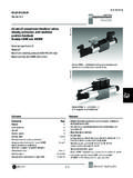
1 RA 23 178 4/3-, 4/2- and 3/2 Directional Control Valves Model WE /E, Series 6X RA. with wet pin AC or DC solenoids 23 178 up to 5100 PSI up to 21 GPM. Size 6 (D 03) (350 bar) (80 L/min) Replaces: Features: Direct operated, solenoid controlled Directional spool valve, heavy duty construction Mounting pattern to ISO/DIS 4401-3 NFPA MR1 and ANSI B D03. Subplates see data sheet RA 45 052. Removable coils for quick replacement, or conversion, in AC or DC voltages Dual frequency solenoids AC voltage with 50 or 60 Hz operation Individual electrical connectors Wet pin core tubes, with high pressure tank capacity, standard. H/A 3972/93. Model 4 WE 24 N9Z45. Functional description 2 5 1 3 5 2.
2 A B. Model 4 WE 6 E 6X/..E. 6 4 A T B 4 6. (P). Directional Control Valves Model WE 6 are solenoid operated Model 4 WE 6 .. 6X/ O (only for spools A, C and D). Directional spool Valves . They Control the start, stop and direction This design permits 2 switching positions with 2 solenoids and no of flow. detent. When the solenoids are de-energised there is no defined They consist of housing (1), one or two solenoids (2), Control spool neutral position. (3) return spring(s) (4). Model 4 WE 6 ..6X/ OF (only for spools A, C and D). Unengaged, Control spool (3) is held centered, by means of return This design permits 2 switching positions with 2 solenoids and spring(s) (4) (except for detented spool).
3 Control spool (3) is shifted detent. Energizing either solenoid, however, only one at a time, by wet pin solenoids (2). To guarantee satisfactory operation, for approx. 100 ms is sufficient to shift spool (3) and maintain a ensure that the solenoid core tube is filled with oil. Cycling the position on the detent. valve will typically ensure core tubes have filled with oil. Orifice Insert (Model 4 WE ). The force of solenoid (2) extends push-pin (5) against Control spool (3), moving it left or right from a neutral position. This provides flow To limit maximum flows, orifice inserts are optionally available. from P to A and B to T or P to B and A to T. Primarily, the orifice insert is intended to prevent flow rates in excess of the maximum performance data of the valve (see page When solenoid (2) is de-energized, Control spool (3) returns to 4).
4 The insert is installed in port P , however, will fit any of the center by return springs (4). valve ports. Manual override (6) allows activating the Control spool (3) without Example: 4 WE 6E 6X/EG24 NDA/B12 = mm orifice in port P . electrical power. P R ring x x 1/10. RA. RA 23. 23 178 178 Ordering codes 2 3 4 6 7 9 10 11 12 15 19 22 23. WE 6 6X E *. 3 service ports =3 Further details 4 service ports =4 in clear text Size 6 =6 No code = NBR seals V= FPM seals Spool C, E, EA, EB etc. 1). For possibilities, see below Attention! The compatibility of the seals and pressure fluid must be taken into account! Series 60 to 69 = 6X No code = Without cartridge throttle (60 to 69: externally interchangeable B 08 = Throttle ( mm).
5 B 10 = Throttle ( mm). Spring return = No code B 12 = Throttle ( mm). Without spring return = O. Applicable if flow exceeds Without spring return but with detent = OF. performance limit of valve, installed in P port High performance solenoid =E. wet pin (oil-immersed) with removable coil Type of electrical connection to data sheet RA 08 006. 24 V DC = G24 Direct solenoid connections 110 V AC 50/60 Hz or = W110 K4 3) = Without angled plug connector(s). 120 V 60 Hz Central solenoid connections DA = Terminal box with 2 1/2" NPT conduit conn. 96/196 V DC solenoid with built-in rectifier, DAL = Terminal box with two 1/2" NPT conduit angled plug, for connection to 110 V/220 V = W110R connections and light(s).
6 AC, frequency-independent ANSI B M plug-pin type (possible with Z55 or conduit box) = W220R connectors (without female end). For other ordering codes for different voltages and frequencies DK23 = Terminal box with 3-pin conn. (single solenoid). see page 3 DK25 = Terminal box with 5-pin conn. (dbl. solenoid). DK23L= Terminal w/ 3-pin conn. & light(s) (sgl. sol.). With protected manual override (Standard) = N9 DK25L= Terminal w/ 5-pin conn. & light(s) (dbl. sol.). Covered manual override, with rubber boot = N DK24L2 = Terminal box w/surge suppression4). Without manual override = No code 3) For additional connectors, see page 9. 4) Surge suppression, 24 VDC only, with 4 pin micro connector Example: 4WE6E6X/E924N9DK24L2.
7 Symbols 1) Example: Spool E with switching position "a". Order code 4 WE6 EA 6X/EW 110 NK4. A B A B A B A B 2). b b b b Symbol E1 : P A/B pre-opening b b P T P T P T P T Caution: Be aware of pressure A B A B A B A B intensification in differential cylinders b b b .. = ). P T P T P T P T =M. A B A B A B A B. b b b =.B. b b .. b =P. P T P T P T P T. =A = E 1). =Q. = E1-2). =C =F =R. =D =G =T. A B A B. b b b =H =U. P T P T. =B =J =V. =Y =L =W. 2/10. RA 23 178 Technical data (For applications outside these parameters please consult us). General Installation position Optional Ambient temperature, max. t F ( C) 122 (50). Weight Single solenoid valve m lbs (kg) ( ).
8 Valve with 2 solenoids m lbs (kg) ( ). Hydraulic Operating pressure Port A, B, P p PSI (bar) 5100 (350). Port T p PSI (bar) up to 3050 (210) DC; up to 2320 (160) AC. Where symbols A and B occur, port T must be employed as a drain port if the operating pressure is above the permitted tank pressure . Flow, max. qV GPM (L/min) up to 21 (80) DC; up to (60) AC. Cross section of flow (switching position 0): for symbol Q A in2 (mm2) approx. 6 % of nominal cross section for symbol W A in2 (mm2) approx. 3 % of nominal cross section Hydraulic fluid Mineral oil (HL, HLP) to DIN 51 524 1); Fast bio-degradable pressure fluids to VDMA 24 568 (also see RA 90 221);. 1) Suitable for NBR and FPM seals HETG (rape seed oil) 1); HEPG (Polyglycol) 2); HEES.
9 2) Only suitable for FPM seals (synthetic ester) 2); other fluids on request Hydraulic fluid t F ( C) 22 to 176 ( 30 to 80) (NBR seals). Temperature range 4 to 176 ( 20 to 80) (FPM seals). Viscosity range SUS (mm2/s) 35 to 2320 ( to 500). Fluid cleanliness Maximum permissible degree of contamination of fluid to ISO 4406 Class 18/15. We therefore recommend a filter with a minimum retention rate of 10 75. Electrical Type of voltage DC voltage AC voltage Available voltages1) (for ordering codes U V 12, 24, 42, 60, 96, 110, 42, 110, 120, 127, 220, 240. for AC voltages see below) 180, 196, 220 50/60 Hz Power consumption P W 30 . Holding current P VA 50. In-rush current P VA 220.
10 Duty cycle continuous continuous Shifting time to ON T ms 25 to 45 10 to 20. ISO 6403 OFF T ms 10 to 25 15 to 40. Shifting frequency Sw/h up to 15000 up to 7200. Insulation Exceeds NEMA class B Exceeds NEMA class B. Coil temperature t F ( C) up to 302 (150) up to 356 (180). 1. ) Special voltages on request When making the electrical connection, the ground screw ( PE) must be connected to earth ground Note on AC solenoids 42 V, 50 Hz 127 V, 50 Hz Order codes Order codes These solenoids may be used with 2 or 3 voltage/frequency W42 W127 127 V, 60 Hz 42 V, 60 Hz relationships: solenoid type W110 for 110 V, 50 Hz 110 V, 50 Hz 220 V, 50 Hz 110 V, 60 Hz W110 110 V, 60 Hz W220 220 V, 60 Hz 120 V, 60 Hz 120 V, 60 Hz 240 V, 60 Hz 3/10.