Transcription of 4/3-, 4/2- and 3/2- directional valves with …
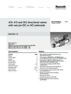
1 RA 23 351 RA 23 351 Replaces: , 4/3-, 4/2- and 3/2- directional valves with switching time adjustment, Model 10. (5-chamber version). Nominal size 10. Series 3X. Maximum operating pressure 4569 PSI (315 bar). HA 5960/98. Maximum flow GPM (120 L/min). Model 10 E3X/CG24N9K4 with plug-in connector Contents Features Description Page Direct solenoid operated spool type directional control valve Features 1 with 5th chamber for dampened adjustable spool shifting Ordering code 2, 3 time Symbols 3 Mounts on standard ISO 4401-5, NFPA/ANSI M R1 D 05, Functional description, section 4, 5 ANSI B D 05 interface Technical data 6 For subplates, see data sheet RA 45 054.
2 Characteristic curves 7 Wet pin DC solenoids (AC possible with rectifier). Performance limits 7 Removable coils for quick replacement, or conversion, in AC or DC. voltages Unit dimensions 8. Individual solenoid plug-in connectors, or central wiring box to Available spare parts and seals 9. NEMA 4 specifications (see data sheet RA 08 002). Optional manual overrides 53 standard spool configurations available Important! The length of the mounting bolt in series 3X/.. is 1-1/2". (40 mm) [formerly 2" ( 50 mm)]. 1/10. RA 23 351 Ordering code 1 2 3 4 6 7 9 10 11 12 15 18 19 22 23.
3 5 WE 10 3X C *. 3 actuator ports =3. 4 actuator ports =4. Nominal size 10 = 10. Symbol C, E, EA, EB etc. for possible versions, see page 3. Series 30 to 39 = 3X. (30 to 39: unchanged installation and connection dimensions). with spring return = No code Without spring return with detent = OF. Without spring return =O. Wet pin solenoid (oil immersed) with removable coil =C. 12 V DC = G12. 24 V DC = G24. 96 V DC = G96 1). For further ordering details regarding other voltages and frequencies, see page 6. with protected manual override (standard) = N9.
4 Without hand override = No code Hand override with protective cap =N. Model of electrical connection Individual connection; with component plug = K4 2). DIN 43 650-AM2, without plug-in connector Without switching time adjustment = No code with adjustable screw (throttle) =C. Orifice in ( mm) = A06. Orifice in ( mm) = A07. Orifice in ( mm) = A08. Without cartridge throttle = No code Throttle in ( mm) = B08. Throttle in ( mm) = B10. Throttle in ( mm) = B12. Throttle in ( mm) Used for flows > performance limits of = B15.
5 Throttle in ( mm) the valve, effective in the P channel = B30. NBR seals = No code FKM seals =V. (other seals on request). Attention! The compatibility of the seals and pressure fluid has to be taken into account! Further details in clear text 1) For the connection to an AC supply a DC solenoid must AC supply Nominal voltage of the be used which is controlled via a rectifier (see table on the left). Order code (permissible voltage DC solenoid tolerance when used with an For individual connections a large plug-in connector with 10%) AC voltage integrated recifier can be used (separate order, see page 3).
6 2) Plug-in connectors must be ordered separately 110 V - 50/60 Hz 96 V G96. (see page 3). 120 V - 60 Hz 110 V G110. 230 V - 50/60 Hz 205 V G205. Attention! The performance limits on page 7 must be taken into account! Rexroth Hydraulics 2/10 10. RA 23 351 Ordering code, plug-in connectors to DIN 43 650 A and ISO 4400 for component plug "K4". For further plug-in connectors see RA 08 006. Material no. with indicator light and Valve with indicator light with LED & rectifier with rectifier Z diode protective circuit side Color Without circuitry 12 240 V 24 240 V 12 240 V 24 V Thread a grey RR00 074683 Pg 11.
7 B black RR00 074684 Pg 11. a/b black RR00 057292 RR00 057423 RR00 313933 RR00 310995 Pg 11. a red/brown RR00 004823 1/2 NPT. b black RR00 011039 1/2 NPT. a/b black RR00 057453 RR00 057455 RR00 842566 1/2 NPT. Symbols A B A B A B A B 1). b b Example: a b a b a 0 b a 0 b a a P T P T P T P T. Spool E with switched position a . A B. a b A B A B Ordering detail .. a b a 0 a 0 = .A 1). P T a P T P T. a b A B A B. a b b 0 b 0 b = .B. P T P T. =A. = E 1) =P. =C. =F =Q. =D. =G =R. A B A B. b a b a b a P T P T =H =T. =B. =J =U.
8 =Y. =L =V. =M =W. 10 3/10 Rexroth Hydraulics RA 23 351 Functional description, section 5-chamber directional valves of model are solenoid operated In order to ensure correct functioning, care must be taken to directional spool valves . They control the start, stop and direction of flow ensure that the pressure chamber of the solenoid is filled with with the additional option of adjusting the spool switching time. oil. These directional valves basically consist of housing (1), one or two The force of solenoid (2) acts on control spool (3) and switches it from solenoids (2), control spool (3), as well as one or two return springs (4).
9 Its rest position to the required end position. This then permits flow from Two spring chambers are connected by a drilling (5). As the spool switches, P to A and B to T or P to B and A to T. the flow is displaced from one spring chamber to the other via this When solenoid (2) is de-energized the control spool (3) is returned to its passage. If the area of this connecting bore is reduced by an orifice, the rest position by return spring (4). switching time changes accordingly. A manual override (6), optional, enables the control spool (3) to be The T channels are isolated from the spring chambers.
10 Switching pulses moved without energization of the solenoids. do not affect control spool (3) and thus, soft switching of the spool can Adjustable spool switching time (only with DC solenoids). be achieved. The optional installation of a throttle screw (7) or orifice (8) - see below In the de-energized condition, control spool (3) is held in the central or - offers the possibility of increasing switching time initial position by return springs (4) (except for impulse spools). The control with throttle screw model 10.