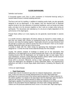
Transcription of 4.5 Procedures for Diaphragms - Memphis
1 For DiaphragmsThis section provides Tier 2 evaluation Procedures thatapply to Diaphragms : general, wood, metal deck,concrete, precast concrete, horizontal bracing, andother 4-27. diaphragm as a BeamFigure 4-28. Chord SectionsChapter - Evaluation Phase (Tier 2)4 - 70 Seismic Evaluation HandbookFEMA 310 Commentary: Diaphragms are horizontal elements that distributeseismic forces to vertical lateral force resistingelements. They also provide lateral support forwalls and parapets. diaphragm forces are derivedfrom the self weight of the diaphragm and theweight of the elements and components that dependon the diaphragm for lateral support. Any roof, floor , or ceiling can participate in the distributionof lateral forces to vertical elements up to the limitof its strength. The degree to which it participatesdepends on relative stiffness and on order to function as a diaphragm , horizontalelements must be interconnected to transfer shear,with connections that have some degree ofstiffness.
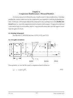
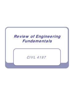
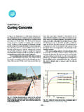
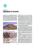
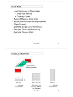
2 An array of loose elements such asceiling tiles, or metal-deck panels attached tobeams with wind clips does not :It is customary to analyze Diaphragms using abeam analogy. The floor , which is analogous tothe web of a wide-flange beam, is assumed to carrythe shear. The edge of the floor , which could be aspandrel or wall, is analogous to the flange, and isassumed to carry the flexural stress. A free-bodydiagram of these elements is shown in Figure diaphragm chord can be a line of edge beamsthat is connected to the floor , or reinforcing in theedge of a slab or in a spandrel. Examples ofchords are shown in Figure BEAMEDGE BEAMSLAB EDGESPANDRELTILT-UP WALLCONTINUOUSSPLICE ATPANEL :BAR IN WALL ORSTEEL LEDGER(NOT SHOWN)WOODLEDGERTwo essential requirements for the chord arecontinuity and connection with the slab.
3 Almostany building with an edge beam has a potentialdiaphragm chord. Even if designed for verticalloads only, the beam end connections probablyhave some capacity to develop horizontal forcesthrough the force in the chord is customarily determined bydividing the moment in the diaphragm by the depthof the diaphragm . This yields an upper bound onthe chord force since it assumes elastic beamFigure 4-29. Rigid and Flexible DiaphragmsFigure 4-30. diaphragm CONTINUITY: Thediaphragms shall not be composed of split-levelChapter - Evaluation Phase (Tier 2)FEMA 310 Seismic Evaluation Handbook4 - 71behavior in the diaphragm and neglects bendingresistance provided by any other components of thediaphragm. A lack of diaphragm damage inpost-earthquake observations provides someevidence that certain Diaphragms may not requirespecific chords as determined by the beam the purpose of this Handbook, the absence ofchords is regarded as a deficiency that warrantsfurther evaluation.
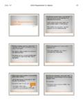
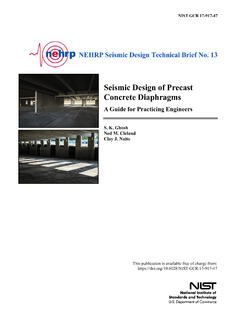
4 Consideration may be given tothe available evidence regarding the suitability ofthe beam analogy and the need for defined chordsin the building being with the beam analogy, a stair orskylight opening may weaken the diaphragm just asa web opening for a pipe may weaken a beam. Anopening at the edge of a floor may weaken thediaphragm just as a notch in a flange weakens FRAMESRIGID WALLSAn important characteristic of Diaphragms isflexibility, or its opposite, rigidity. In seismicdesign, rigidity means relative rigidity. Ofimportance is the in-plane rigidity of the diaphragmrelative to the walls or frame elements that transmitthe lateral forces to the ground (Figure 4-29). Aconcrete floor is relatively rigid compared to steelmoment frames, whereas a metal deck roof isrelatively flexible compared to concrete or masonrywalls.
5 Wood Diaphragms are generally treated asflexible, but consideration must be given to rigidityof the vertical elements. Wood Diaphragms maynot be flexible compared to wood shear wall panelsin a given building. Another consideration is continuity overintermediate supports. In a three-bay building, forexample, the diaphragm has three spans and foursupports. If the diaphragm is relatively rigid, thechords should be continuous over the supports likeflanges of a continuous beam over intermediatesupports. If the diaphragm is flexible, it may bedesigned as a simple beam spanning between wallswithout consideration of continuity of the the latter case, the design professional shouldremember that the diaphragm is really continuous,and that this continuity is simply being neglected. XYYYXYCOLLECTORCRTICALCONNECTION floors.
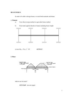
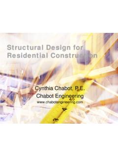
6 In wood buildings, the Diaphragms shall nothave expansion 2 Evaluation Procedure: The load path aroundthe discontinuity shall be identified. The diaphragmshall be analyzed for the forces in Section and theadequacy of the elements in the load path shall beevaluated. CROSS TIES: There shall be continuouscross ties between diaphragm 2 Evaluation Procedure: Out-of-plane forces inaccordance with Section shall be calculated. Theadequacy of the existing connections, includingdevelopment of the forces into the diaphragm , shall 4-31. Cross TiesChapter - Evaluation Phase (Tier 2)4 - 72 Seismic Evaluation HandbookFEMA 310 Figure 4-30 (on previous page) shows a diaphragmof two spans that may or may not be continuousover the intermediate support. If chord continuity isdeveloped at the points marked X, these will be thelocations of maximum chord force.
7 If chordcontinuity is not provided at X, the spans will actas two simple beams. The maximum chord forcewill occur at the middle of each span, at the pointsmarked Y. The end rotations of the two spans maycause local damage at points , there must be an adequate mechanism forthe transfer of diaphragm shear forces to thevertical elements. This topic is addressed in detailin Section An important element related todiaphragm force transfer is the collector, or dragstrut. In Figure 4-31, a member is added to collectthe diaphragm shear and drag it into the shortintermediate shear wall. The presence of acollector avoids a concentration of stress in thediaphragm at the short shear wall. Collectors mustbe continuous across any interrupting elementssuch as perpendicular beams, and must beadequately connected to the shear wall to deliverforces into the buildings of more than one story, the designprofessional must consider the effect of flexiblediaphragms on walls perpendicular to the directionof seismic force under : Split level floors and roofs, or diaphragmsinterrupted by expansion joints, creatediscontinuities in the diaphragm .
8 This condition iscommon in ramped parking structures. It is aproblem unless special details are used, orlateral-force-resisting elements are provided at thevertical offset of the diaphragm or on both sides ofthe expansion joint. Such a discontinuity maycause the diaphragm to function as a cantileverelement or three-sided diaphragm . If thediaphragm is not supported on at least three sidesby lateral-force-resisting elements, torsional forcesin the diaphragm may cause it to become both the cantilever and three-sided cases,increased lateral deflection in the discontinuousdiaphragm may cause increased damage to, orcollapse of, the supporting the load path is incomplete, mitigation withelements or connections required to complete theload path is necessary to achieve the selectedperformance :Continuous crossties between diaphragm chordsare needed to develop out-of-plane wall forces intothe diaphragm (see Figure 4-31).
9 The crosstiesshould have a positive and direct connection to thewalls to keep the walls from separating from thebuilding. The connection of the crosstie to thewall, and connections within the crosstie, must bedetailed so that cross-grain bending or cross-graintension does not occur in any wood member (seeSection ). ROOF CHORD CONTINUITY: All chordelements shall be continuous, regardless of changesin roof 2 Evaluation Procedure: The load path aroundthe discontinuity shall be identified. The diaphragmshall be analyzed for the forces in Section and the adequacy of the elements in the load path shall beevaluated. Figure 4-32. Roof Chord OPENINGS AT SHEAR WALLS: diaphragm openings immediately adjacent to theshear walls shall be less than 25% of the wall lengthfor Life Safety and 15% of the wall length forImmediate 2 Evaluation Procedure: The in-plane sheartransfer demand at the wall shall be calculated.
10 Theadequacy of the diaphragm to transfer loads to the wallshall be evaluated considering the available length andthe presence of any drag struts. The adequacy of thewalls to span out-of-plane between points of anchorageshall be evaluated and the adequacy of the diaphragmconnections to resist wall out-of-plane forces shall beevaluated. Figure 4-33. Opening at Exterior WallChapter - Evaluation Phase (Tier 2)FEMA 310 Seismic Evaluation Handbook4 - 73 Commentary: Diaphragms with discontinuous chords will bemore flexible and will experience more damagearound the perimeter than properly detaileddiaphragms. Vertical offsets or elevation changesin a diaphragm often cause a chord discontinuity(see Figure 4-32). To provide continuity thefollowing elements are required: a continuouschord element; plane X to connect the offsetportions of the diaphragm ; plane Y to develop thesloping diaphragm into the chord; and verticalINTERMEDIATEWALL ANCHORAT CROSS TIECROSS TIEWALL ANCHOR.