Transcription of 4.5 Ω typical on resistance - Analog Devices
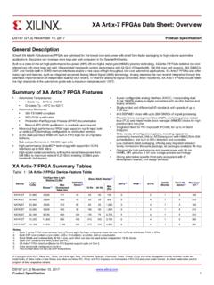
1 RON, 16- channel , Differential 8- channel , 5 V,+12 V,+5 V, and + V Multiplexers Data Sheet ADG1606/ADG1607 Rev. A Document Feedback Information furnished by Analog Devices is believed to be accurate and reliable. However, no responsibility is assumed by Analog Devices for its use, nor for any infringements of patents or other rights of third parties that may result from its use. Specifications subject to change without notice. No license is granted by implication or otherwise under any patent or patent rights of Analog Devices . Trademarks and registered trademarks are the property of their respective owners. One Technology Way, Box 9106, Norwood, MA 02062-9106, Tel: 2009 2016 Analog Devices , Inc. All rights reserved. Technical Support FEATURES typical on resistance on resistance flatness V to 8 V dual supply operation V to 16 V single supply operation No VL supply required 3 V logic-compatible inputs Rail-to-rail operation Up to 378 mA of continuous current per channel 28-lead TSSOP and 32-lead, 5 mm 5 mm LFCSP APPLICATIONS Communication systems Medical systems Audio signal routing Video signal routing Automatic test equipment Data acquisition systems Battery-powered systems Sample-and-hold systems Relay replacements FUNCTIONAL BLOCK DIAGRAMS 1-OF-16 DECODERA0A1A2A3 ENADG1606S1S16D08489-001 Figure 1.
2 1-OF-8 DECODERA0A1A2 ENADG1607S1BS8 BDBS1AS8 ADA08489-002 Figure 2. GENERAL DESCRIPTION The ADG1606 and ADG1607 are monolithic iCMOS Analog multiplexers comprising of 16 single channels and eight differential channels, respectively. The ADG1606 switches one of 16 inputs to a common output, as determined by the 4-bit binary address lines (A0, A1, A2, and A3). The ADG1607 switches one of eight differential inputs to a common differential output, as determined by the 3-bit binary address lines (A0, A1, and A2). An EN input on both Devices enables or disables the device. When disabled, all channels switch off. When enabled, each channel conducts equally well in both directions and has an input signal range that extends to the supplies. The ultralow on resistance and on- resistance flatness of these switches make them ideal solutions for data acquisition and gain switching applications where low distortion is critical. iCMOS construction ensures ultralow power dissipation, making the parts ideally suited for portable and battery-powered instruments.
3 PRODUCT HIGHLIGHTS 1. maximum on resistance over temperature. 2. Minimum distortion: THD + N = 3. 3 V logic-compatible digital inputs: VINH = V, VINL = V. 4. No VL logic power supply required. ADG1606/ADG1607 Data Sheet Rev. A | Page 2 of 22 TABLE OF CONTENTS Features .. 1 Applications .. 1 Functional Block Diagrams .. 1 General Description .. 1 Product Highlights .. 1 Revision History .. 2 Specifications .. 3 5 V Dual Supply .. 3 12 V Single Supply .. 4 5 V Single Supply .. 5 V Single Supply .. 6 Continuous Current per channel , S or D ..7 Absolute Maximum Ratings ..8 Thermal resistance ..8 ESD Pin Configurations and Function Descriptions ..9 typical Performance Characteristics .. 13 Test Circuits .. 17 Terminology .. 20 Outline Dimensions .. 21 Ordering Guide .. 21 REVISION HISTORY 8/2016 Rev. 0 to Rev. A Changed CP-32-2 to CP-32-7 .. Throughout Changes to Figure 4 .. 9 Changes to Figure 6 .. 11 Updated Outline Dimensions .. 21 Changes to Ordering Guide.
4 21 10/2009 Revision 0: Initial Version Data Sheet ADG1606/ADG1607 Rev. A | Page 3 of 22 SPECIFICATIONS 5 V DUAL SUPPLY VDD = +5 V 10%, VSS = 5 V 10%, GND = 0 V, unless otherwise noted. Table 1. Parameter 25 C 40 C to +85 C 40 C to +125 C Unit Test Conditions/Comments Analog SWITCH Analog Signal Range VDD to VSS V On resistance (RON) typ VS = V, IS = 10 mA; see Figure 26 max VDD = V, VSS = V On resistance Match Between Channels ( RON) typ VS = V, IS = 10 mA max On resistance Flatness (RFLAT(ON)) typ VS = V, IS = 10 mA 2 max LEAKAGE CURRENTS VDD = + V, VSS = V Source Off Leakage, IS (Off) nA typ VS = V, VD = V; see Figure 27 3 nA max Drain Off Leakage, ID (Off) nA typ VS = V, VD = V; see Figure 27 ADG1606 3 25 nA max channel On Leakage, ID, IS (On) nA typ VS = VD = V; see Figure 28 3 25 nA max DIGITAL INPUTS Input High Voltage, VINH V min Input Low Voltage, VINL V max Input Current, IINL or IINH A typ VIN = VGND or VDD A max Digital Input Capacitance, CIN 4 pF typ DYNAMIC CHARACTERISTICS1 Transition Time, tTRANSITION 175 ns typ RL = 300 , CL = 35 pF 214 247 275 ns max VS = V; see Figure 29 tON (EN) 132 ns typ RL = 300 , CL = 35 pF 162 180 188 ns max VS = V; see Figure 31 tOFF (EN) 124 ns typ RL = 300 , CL = 35 pF 153 176 202 ns max VS = V; see Figure 31 Break-Before-Make Time Delay, tBBM 42 ns typ RL = 300 , CL = 35 pF 15 ns min VS1 = VS2 = V; see Figure 30 Charge Injection 27 pC typ VS = 0 V, RS = 0 , CL = 1 nF; see Figure 32 Off Isolation 62 dB typ RL = 50 , CL = 5 pF, f = 1 MHz; see Figure 33 channel -to- channel Crosstalk 62 dB typ RL = 50 , CL = 5 pF, f = 1 MHz.
5 See Figure 35 Total Harmonic Distortion + Noise (THD + N) % typ RL = 110 , 5 V p-p, f = 20 Hz to 20 kHz; see Figure 36 3 dB Bandwidth RL = 50 , CL = 5 pF; see Figure 34 ADG1606 21 MHz typ ADG1607 37 MHz typ CS (Off) 18 pF typ VS = 0 V, f = 1 MHz CD (Off) ADG1606 248 pF typ VS = 0 V, f = 1 MHz ADG1607 123 pF typ VS = 0 V, f = 1 MHz CD, CS (On) ADG1606 271 pF typ VS = 0 V, f = 1 MHz ADG1607 146 pF typ VS = 0 V, f = 1 MHz POWER REQUIREMENTS VDD = + V, VSS = V IDD A typ Digital inputs = 0 V or VDD A max VDD/VSS 8 V min/max 1 Guaranteed by design, not subject to production test. ADG1606/ADG1607 Data Sheet Rev. A | Page 4 of 22 12 V SINGLE SUPPLY VDD = 12 V 10%, VSS = 0 V, GND = 0 V, unless otherwise noted. Table 2. Parameter 25 C 40 C to +85 C 40 C to +125 C Unit Test Conditions/Comments Analog SWITCH Analog Signal Range 0 V to VDD V On resistance (RON) 4 typ VS = 0 V to 10 V, IS = 10 mA; see Figure 26 5 7 max VDD = V, VSS = 0 V On resistance Match Between Channels ( RON) typ VS = 10 V, IS = 10 mA max On resistance Flatness (RFLAT(ON)) 1 typ VS = 0 V to 10 V, IS = 10 mA max LEAKAGE CURRENTS VDD = V, VSS = 0 V Source Off Leakage, IS (Off) nA typ VS = 1 V/10 V, VD = 10 V/1 V; see Figure 27 3 nA max Drain Off Leakage, ID (Off) nA typ VS = 1 V/10 V, VD = 10 V/1 V; see Figure 27 ADG1606 3 25 nA max channel On Leakage, ID, IS (On) nA typ VS = VD = 1 V or 10 V.
6 See Figure 28 3 25 nA max DIGITAL INPUTS Input High Voltage, VINH V min Input Low Voltage, VINL V max Input Current, IINL or IINH A typ VIN = VGND or VDD A max Digital Input Capacitance, CIN 4 pF typ DYNAMIC CHARACTERISTICS1 Transition Time, tTRANSITION 143 ns typ RL = 300 , CL = 35 pF 170 198 221 ns max VS = 8 V; see Figure 29 tON (EN) 108 ns typ RL = 300 , CL = 35 pF 128 136 142 ns max VS = 8 V; see Figure 31 tOFF (EN) 90 ns typ RL = 300 , CL = 35 pF 109 132 150 ns max VS = 8 V; see Figure 31 Break-Before-Make Time Delay, tBBM 40 ns typ RL = 300 , CL = 35 pF 15 ns min VS1 = VS2 = 8 V; see Figure 30 Charge Injection 33 pC typ VS = 6 V, RS = 0 , CL = 1 nF; see Figure 32 Off Isolation 62 dB typ RL = 50 , CL = 5 pF, f = 1 MHz; see Figure 33 channel -to- channel Crosstalk 62 dB typ RL = 50 , CL = 5 pF, f = 1 MHz; see Figure 35 Total Harmonic Distortion + Noise (THD + N) % typ RL = 110 , 5 V p-p, f = 20 Hz to 20 kHz; see Figure 36 3 dB Bandwidth RL = 50 , CL = 5 pF; see Figure 34 ADG1606 22 MHz typ ADG1607 38 MHz typ CS (Off) 18 pF typ VS = 6 V, f = 1 MHz CD (Off) ADG1606 240 pF typ VS = 6 V, f = 1 MHz ADG1607 120 pF typ VS = 6 V, f = 1 MHz CD, CS (On) ADG1606 263 pF typ VS = 6 V, f = 1 MHz ADG1607 143 pF typ VS = 6 V, f = 1 MHz POWER REQUIREMENTS VDD = 12 V IDD A typ Digital inputs = 0 V or VDD A max ADG1606 300 A typ Digital inputs = 5 V 480 A max ADG1607 370 A typ Digital inputs = 5 V 600 A max VDD V min/max 1 Guaranteed by design, not subject to production test.
7 Data Sheet ADG1606/ADG1607 Rev. A | Page 5 of 22 5 V SINGLE SUPPLY VDD = 5 V 10%, VSS = 0 V, GND = 0 V, unless otherwise noted. Table 3. Parameter 25 C 40 C to +85 C 40 C to +125 C Unit Test Conditions/Comments Analog SWITCH Analog Signal Range 0 V to VDD V On resistance (RON) typ VS = 0 V to V, IS = 10 mA; see Figure 26 max VDD = V, VSS = 0 V On resistance Match Between Channels ( RON) typ VS = 0 V to V, IS = 10 mA max On resistance Flatness (RFLAT(ON)) typ VS = 0 V to V, IS = 10 mA 3 max LEAKAGE CURRENTS VDD = V, VSS = 0 V Source Off Leakage, IS (Off) nA typ VS = 1 V, VD = V/1 V; see Figure 27 3 nA max Drain Off Leakage, ID (Off) nA typ VS = 1 V, VD = V/1 V; see Figure 27 ADG1606 3 25 nA max channel On Leakage, ID, IS (On) nA typ VS = VD = 1 V or V; see Figure 28 3 25 nA max DIGITAL INPUTS Input High Voltage, VINH V min Input Low Voltage, VINL V max Input Current, IINL or IINH A typ VIN = VGND or VDD A max Digital Input Capacitance, CIN 4 pF typ DYNAMIC CHARACTERISTICS1 Transition Time, tTRANSITION 220 ns typ RL = 300 , CL = 35 pF 280 324 360 ns max VS = V; see Figure 29 tON (EN) 160 ns typ RL = 300 , CL = 35 pF 202 221 234 ns max VS = V; see Figure 31 tOFF (EN) 154 ns typ RL = 300 , CL = 35 pF 197 232 259 ns max VS = V; see Figure 31 Break-Before-Make Time Delay, tBBM 45 ns typ RL = 300 , CL = 35 pF 15 ns min VS1 = VS2 = V; see Figure 30 Charge Injection 12 pC typ VS = V, RS = 0 , CL = 1 nF; see Figure 32 Off Isolation 62 dB typ RL = 50 , CL = 5 pF, f = 1 MHz; see Figure 33 channel -to- channel Crosstalk 62 dB typ RL = 50 , CL = 5 pF, f = 1 MHz.
8 See Figure 35 Total Harmonic Distortion + Noise (THD + N) % typ RL = 110 , f = 20 Hz to 20 kHz, VS = V p-p; see Figure 36 3 dB Bandwidth RL = 50 , CL = 5 pF; see Figure 34 ADG1606 19 MHz typ ADG1607 34 MHz typ CS (Off) 20 pF typ VS = V, f = 1 MHz CD (Off) ADG1606 270 pF typ VS = V, f = 1 MHz ADG1607 137 pF typ VS = V, f = 1 MHz CD, CS (On) ADG1606 300 pF typ VS = V, f = 1 MHz ADG1607 160 pF typ VS = V, f = 1 MHz POWER REQUIREMENTS VDD = V IDD A typ Digital inputs = 0 V or VDD A max VDD V min/max 1 Guaranteed by design, not subject to production test. ADG1606/ADG1607 Data Sheet Rev. A | Page 6 of 22 V SINGLE SUPPLY VDD = V, VSS = 0 V, GND = 0 V, unless otherwise noted. Table 4. Parameter 25 C 40 C to +85 C 40 C to +125 C Unit Test Conditions/Comments Analog SWITCH Analog Signal Range 0 V to VDD V On resistance (RON) 14 typ VS = 0 V to VDD, IS = 10 mA; see Figure 26 VDD = V, VSS = 0 V On resistance Match Between Channels ( RON) typ VS = 0 V to VDD, IS = 10 mA On resistance Flatness (RFLAT(ON)) 5 6 typ VS = 0 V to VDD, IS = 10 mA LEAKAGE CURRENTS VDD = V, VSS = 0 V Source Off Leakage, IS (Off) nA typ VS = V/3 V, VD = 3 V; see Figure 27 3 nA max Drain Off Leakage, ID (Off) nA typ VS = V/3 V, VD = 3 V; see Figure 27 ADG1606 3 25 nA max channel On Leakage, ID, IS (On) nA typ VS = VD = V or 3 V.
9 See Figure 28 3 25 nA max DIGITAL INPUTS Input High Voltage, VINH V min Input Low Voltage, VINL V max Input Current, IINL or IINH A typ VIN = VGND or VDD A max Digital Input Capacitance, CIN 4 pF typ DYNAMIC CHARACTERISTICS1 Transition Time, tTRANSITION 353 ns typ RL = 300 , CL = 35 pF 482 536 575 ns max VS = V; see Figure 29 tON (EN) 263 ns typ RL = 300 , CL = 35 pF 362 385 396 ns max VS = V; see Figure 31 tOFF (EN) 262 ns typ RL = 300 , CL = 35 pF 348 391 424 ns max VS = V; see Figure 31 Break-Before-Make Time Delay, tBBM 74 ns typ RL = 300 , CL = 35 pF 15 ns min VS1 = VS2 = V; see Figure 30 Charge Injection 6 pC typ VS = V, RS = 0 , CL = 1 nF; see Figure 32 Off Isolation 62 dB typ RL = 50 , CL = 5 pF, f = 1 MHz; see Figure 33 channel -to- channel Crosstalk 62 dB typ RL = 50 , CL = 5 pF, f = 1 MHz; see Figure 35 Total Harmonic Distortion + Noise (THD + N) % typ RL = 110 , f = 20 Hz to 20 kHz, VS = 2 V p-p; see Figure 36 3 dB Bandwidth RL = 50 , CL = 5 pF; see Figure 34 ADG1606 17 MHz typ ADG1607 31 MHz typ CS (Off) 22 pF typ VS = V, f = 1 MHz CD (Off) ADG1606 290 pF typ VS = V, f = 1 MHz ADG1607 145 pF typ VS = V, f = 1 MHz CD, CS (On) ADG1606 350 pF typ VS = V, f = 1 MHz ADG1607 168 pF typ VS = V, f = 1 MHz POWER REQUIREMENTS VDD = V IDD A typ Digital inputs = 0 V or VDD A max VDD V min/max 1 Guaranteed by design, not subject to production test.
10 Data Sheet ADG1606/ADG1607 Rev. A | Page 7 of 22 CONTINUOUS CURRENT PER channel , S OR D Table 5. ADG1606 Parameter 25 C 85 C 125 C Unit CONTINUOUS CURRENT, S OR D VDD = +5 V, VSS = 5 V TSSOP ( JA = C/W) 259 168 105 mA maximum LFCSP ( JA = 46 C/W) 357 217 122 mA maximum VDD = 12 V, VSS = 0 V TSSOP ( JA = C/W) 273 175 108 mA maximum LFCSP ( JA = 46 C/W) 378 224 122 mA maximum VDD = 5 V, VSS = 0 V TSSOP ( JA = C/W) 199 136 91 mA maximum LFCSP ( JA = 46 C/W) 276 178 108 mA maximum VDD = V, VSS = 0 V TSSOP ( JA = C/W) 164 119 80 mA maximum LFCSP ( JA = 46 C/W) 227 154 98 mA maximum Table 6. ADG1607 Parameter 25 C 85 C 125 C Unit CONTINUOUS CURRENT, S OR D VDD = +5 V, VSS = 5 V TSSOP ( JA = C/W) 192 133 91 mA maximum LFCSP ( JA = 46 C/W) 266 175 108 mA maximum VDD = 12 V, VSS = 0 V TSSOP ( JA = C/W) 203 140 91 mA maximum LFCSP ( JA = 46 C/W) 280 178 108 mA maximum VDD = 5 V, VSS = 0 V TSSOP ( JA = C/W) 147 108 70 mA maximum LFCSP ( JA = 46 C/W) 206 140 94 mA maximum VDD = V, VSS = 0 V TSSOP ( JA = C/W) 122 91 56 mA maximum LFCSP ( JA = 46 C/W) 168 119 84 mA maximum ADG1606/ADG1607 Data Sheet Rev.