Transcription of 4” & 6” Suspension System
1 4 & 6 Suspension SystemChevrolet/GMC K1500 4WD | 2007-2013 Rev. 061317 Part#: 021644491 W. Garfield Ave., Coldwater, MI 49036 . Phone: | 021644 Read And Understand All Instructions And Warnings Prior To Installation Of System And Operation Of YOU STARTBDS Suspension Co. recommends this System be installed by a professional technician. In addition to these instructions, professional knowledge of disassembly/ reassembly procedures and post installation checks must be YOUR SAFETYC ertain BDS Suspension products are intended to improve off-road per-formance. Modifying your vehicle for off-road use may result in the vehicle handling differently than a factory equipped vehicle. Extreme care must be used to prevent loss of control or vehicle rollover.
2 Failure to drive your modified vehicle safely may result in serious injury or death. BDS Suspension Co. does not recommend the combined use of Suspension lifts, body lifts, or other lifting devices. You should never operate your modified vehicle under the influence of alcohol or drugs. Always drive your modified vehicle at re-duced speeds to ensure your ability to control your vehicle under all driving conditions. Always wear your seat INSTALLATIONS pecial literature required: OE Service Manual for model/year of vehicle. Refer to manual for proper disassembly/reassembly procedures of OE and related to recommendations when replacement fasteners, retainers and keepers are called out in the OE rim and tire combinations may increase leverage on Suspension , steering, and related components.
3 When selecting combinations larger than OE, consider the additional stress you could be inducing on the OE and related Suspension System vehicles may experience drive line vibrations. Angles may require tuning, slider on shaft may require replacement, shafts may need to be lengthened or trued, and U-joints may need to be and properly block vehicle prior to installation of BDS Suspension components. Always wear safety glasses when using power installation is to be performed without a hoist, BDS Suspension Co. recom-mends rear alterations to payload options and initial ride height variances, the amount of lift is a base figure. Final ride height dimensions may vary in accordance to original vehicle attitude. Always measure the attitude prior to beginning truck is about to be fitted with the best Suspension System on the market today.
4 That means you will be driving the baddest looking truck in the neighborhood, and you ll have the warranty to ensure that it stays that way for years to come. Thank you for choosing BDS Suspension !BEFORE YOU DRIVEC heck all fasteners for proper torque. Check to ensure for adequate clearance between all rotating, mobile, fixed, and heated members. Verify clearance between exhaust and brake lines, fuel lines, fuel tank, floor boards and wiring harness. Check steering gear for clearance. Test and inspect brake steering sweep to ensure front brake hoses have adequate slack and do not contact any rotating, mobile or heated members. Inspect rear brake hoses at full extension for adequate slack. Failure to perform hose check/ replacement may result in component failure.
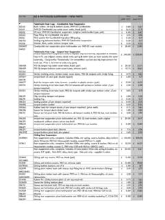
5 Longer replacement hoses, if needed can be purchased from a local parts head light check and all fasteners after 500 miles. Always inspect fasteners and compo-nents during routine GUIDE 6 on 17x8 with 4-1/2 on 17x9 or 18x9 with 5 on 20x9 with backspacing4 on 17x8 with 4-1/2 on 17x9 or 18x9 with 5 on 20x9 with backspacing021644 | 3021644 Box KitPart #QtyDescription021601 Steering Knuckle (drv)021611 Steering Knuckle (pass)021761 Front Crossmember021771 Rear Crossmember023251 Differential Drop Bracket (drv)021651 Differential Drop Bracket (pass)021662 Sway Bar Drop Bracket981611 Front Strut Kit (6" Kit)981411 Front Strut Kit (4" Kit)021751 Differential Skid Plate021861 Splash Guard014992 Splash Guard Spacer021691 Weld-In Plate011652CV Spacer021151 Brake Line Extension (drv)021161 Brake Line Extension (pass)
6 "-18 x 3/4" boltN56SS25/16"-18 hex nutLW5625/16" lock washerW56 SAE25/16" SAE flat washer33962 Bump Stop ExtensionSBLA1 Brake Line Extension3427011 Loctite0990007 Zip Ties021644 Box Kit6211 Bolt Pack (x-member hardware)25/8"-11 x 4-1/2" bolt grade 8 yellow zinc25/8"-11 x 5-1/2" bolt grade 8 yellow zinc45/8"-11 prevailing torque nut yellow zinc85/8" SAE flat washer thru-hardened yellow zinc6071 Bolt Pack (front main)41/2"-13 x 1-1/4" bolt grade 8 yellow zinc41/2"-13 x 1-3/4" bolt grade 8 yellow zinc31/2"-13 x 3" bolt grade 8 yellow zinc91/2"-13 prevailing torque nut yellow zinc181/2" SAE washer thru-hardened yellow zinc21-3/8"OD x 1/2"ID x 3/16" thk flat washer clear x 130mm bolt class clear x 70mm bolt grade clear zinc1610mm flat washer clear zinc4 Wire Clip (Fastenal #0708762)21/4"-20 x 3/4" bolt grade 5 clear zinc21/4" split lock washer clear zinc21/4" SAE washer clear zinc6281 Bolt Pack (rear kit)
7 15/16" x 1 bolt grade 5 clear zinc 1 5/16"-18 prevailing torque nut clear zinc 2 5/16" SAE flat washer clear zinc 2 x 110mm Allen head bolt black oxide011559 Rear Block and Add-A-LeafPart #QtyDescription111209R2 Add-A-Leaf06940924" Block22800313/8" Center Pin KitUBT404549/16" x 2-1/2" x 11-3/8" U-bolt Kit011457 Rear Kit - BlockPart #QtyDescriptionBB08825" BlockUBT414549/16" x 2-1/2" x 12-1/2 " U-bolt KitPICKUP SYSTEMTAHOE, YUKON, AVALANCHE, SUBURBAN SYSTEM4 | 021644 FRONT INSTALLATION1. Park the vehicle on a clean, flat surface and block the rear wheels for Disconnect the positive and negative battery cables from the bat-ter Raise the front of the vehicle with a hydraulic jack and support the frame with jack stands just behind the rear lower control arm Remove the Disconnect the ABS line from the connector on the frame (Fig 1).
8 Remove the ABS line from the retaining clips at the frame, upper control arm and Disconnect the brake line bracket from the upper control arm (Fig 1). Retain 17. Disconnect the steering from the knuckle (Fig 2). Remove the tie rod end nut. Strike the knuckle near the tie rod end with a hammer to dislodge it. Retain the mounting Quality Strut CompressorWelderTROUBLESHOOTING INFORMATION FOR YOUR VEHICLE1. Will not fit 2007 classic Requires frame bracket modification and minor 20 wheels with 5-3/4 backspacing recommended to reduce AWD models may require front driveline Will not fit two mode hybrid models with electronic power Will not work with auto-ride equipped Rear Kit Replacement SpringPart #QtyDescription0015592 Rear SpringUBT403749/16" x 2-1/2" x 10" U-bolt Kit0710072 Spring Bushing Kit011458 - Rear Kit - Replacement SpringPart #QtyDescription0015592 Rear SpringUBT403649/16" x 2-1/2" x 8-3/4" U-bolt Kit0710072 Spring Bushing Kit021644 | 5 FIGURE 28.
9 Remove the two brake caliper mount bolts and remove the caliper assembly from the knuckle (Fig 3). Hang the caliper securely out of the way. DO NOT hang the caliper by the brake 39. Remove the hub dust cap (Fig 4). Remove the axle shaft nut. Retain nut and cap. Remove brake 410. Remove the sway bar links from the sway bar and the lower control arm (Fig 5). Retain the links, bushings and | 021644 FIGURE 511. Remove the sway bar from the frame by removing the four bushing cap mounting bolts (Fig 6). Retain all sway bar 612. Mark each of the front strut bodies to indicate driver s verses passenger s side. Make the marks on the side of the strut that is facing Support the lower control arm with a jack. Remove the lower strut mount bolts (Fig 7).
10 Retain 7021644 | 714. Remove the CV shaft mounting flange nuts (Fig 8). Mark the shaft to indicate driver s or passenger s side. Discard 815. Remove the upper and lower ball joint nuts and thread back on by hand a couple of turns. Strike the knuckle near the upper and lower ball joints to dislodge them from the knuckle. Remove the upper ball joint nut and lower the lower control arm down. Remove the CV shaft from the hub and set aside. Remove the lower ball joint nut and remove the knuckle assembly from the lower control Remove the front and rear lower control arm mounting bolts and remove the lower control arm from the vehicle. Retain mounting Remove the three upper strut mounting nuts (Fig 9) and remove the strut from the vehicle.