Transcription of 4-Bit Register Memory 1 - Virginia Tech
1 Memory1 Built using D flip-flops: 4-Bit RegisterIntro Computer OrganizationComputer Science Dept Va Tech March 2006 2006 McQuain & RibbensClock input controls when input is "written" to the individual , the design above isn t quite what we What s wrong with this?How can we fix it?Memory2A Register fileis a collection of kregisters (a sequential logic block) that can be read and written by specifying a Register number that determines which Register is to be FileThe interface should minimally include:- an n-bit input to import data for writing (a write port)-an n-bit output to export read data (a read port)Intro Computer OrganizationComputer Science Dept Va Tech March 2006 2006 McQuain & Ribbens-an n-bit output to export read data (a read port)- a log(k)-bit input to specify the Register number- control bit(s) to enable/disable read/write operations- a control bit to clear all the registers, asynchronously- a clock signalSome designs may provide multiple read or write ports, and additional MIPS, it is convenient to have two read ports and one write port.
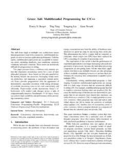
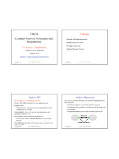
2 Why?Memory3 Aggregating a collection of 4-Bit registers, and providing the appropriate Register selection and data input/output interface:A File of 4-Bit Registers4-bit registersdecoder to select write registermultiplexor to select read registerIntro Computer OrganizationComputer Science Dept Va Tech March 2006 2006 McQuain & RibbensregisterMemory4 Random Access MemoryRandom access Memory (RAM) is an array of Memory RAM(SRAM): - bits are stored as flip-flops (typically 4 or more transistors per bit)- hence static in the sense that the value is preserved as long as power is supplied- somewhat complex circuit per bit, so not terribly dense on chip- typically used for cache memoryIntro Computer OrganizationComputer Science Dept Va Tech March 2006 2006 McQuain & RibbensDynamic RAM(DRAM): - bits are stored as a charge in a capacitor- hence dynamic since periodic refreshes are needed to maintain stored values- singletransistor needed per data bit, so very dense in comparison to SRAM- much cheaper per bit than SRAM- much slower access time than SRAM- typically used for main memoryMemory5 Basic MIPS ImplementationHere's an updated view of the basic architecture needed to implement a subset of the MIPS environment:RAM modulesIntro Computer OrganizationComputer Science Dept Va Tech March 2006 2006 McQuain & Ribbensregister fileMemory6 SRAMsConfiguration specified by the # of addressable locations (# of rows or height) and the # of bits stored in each location (width).
3 Consider a 4M x 8 SRAM:- 4M locations, each storing 8 bits- 22 address bits to specify the location for a read/write- 8-bit data output line and 8-bit data input lineEnable/disable chip access16-bit output path21-bit address inputIntro Computer OrganizationComputer Science Dept Va Tech March 2006 2006 McQuain & RibbensaccessEnable/disable read and write access16-bit wide input pathMemory7 SRAM Performanceread access time- the delay from the time the Output enable is true and the address lines are valid until the time the data is on the output typical read access times might be from 2-4 ns to 8-20 ns, or considerably greater for low-power versions developed for consumer access time- set-up and hold-time requirements for both the address and data lines-write-enable signal is actually a pulse of some minimum width, rather than a clock Intro Computer OrganizationComputer Science Dept Va Tech March 2006 2006 McQuain & Ribbens-write-enable signal is actually a pulse of some minimum width, rather than a clock edge- write access time includes all of theseMemory8 SRAM ImplementationAlthough the SRAM is conceptually similar to a Register file.
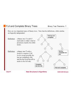
4 - impractical to use same design due to the unreasonable size of the multiplexors that would be needed- design is based on a three-state bufferdata signaloutput enablemultiplexor build from 3-state buffer elementsIntro Computer OrganizationComputer Science Dept Va Tech March 2006 2006 McQuain & RibbensIf output enable is 1, then the buffer's output equals its input data output enable is 0, then the buffer's output is in a high-impedance state that effectively disables its effect on the bit line to which it is ImplementationAt right is a conceptual representation of a 4x2 SRAM unit built from D latches that incorporate 3-state simplicity, the chip select and output enable signals have been omitted. Intro Computer OrganizationComputer Science Dept Va Tech March 2006 2006 McQuain & RibbensAlthough this eliminates the need for a multiplexor, the decoder that IS required will become excessively large if we scale this up to a useful ImplementationA 4Mx8 SRAM as an array of 4Kx1024 arrays:decoder generates addresses for the 4096 rows of each of the 8 subarrayseach subarray outputs a row of 1024 bitsbank of 10-bit Intro Computer OrganizationComputer Science Dept Va Tech March 2006 2006 McQuain & RibbensThis requires neither a huge multiplexor nor a huge practical version might use a larger number of smaller subarrays.
5 How would that affect the dimensions of the decoder and multiplexors that would be needed?of 1024 bitsbank of 10-bit multiplexors select one bit from each of the subarraysMemory11 DRAM ImplementationEach bit is stored as a charge on a refreshes are necessary and typically require 1-2% of the cycles of a DRAM uses a 2-level decoding scheme; a row Intro Computer OrganizationComputer Science Dept Va Tech March 2006 2006 McQuain & RibbensAccess uses a 2-level decoding scheme; a row accessselects and transfers a row of values to a row of latches; a column accessthen selects the desired data from the uses the column access times typically range from 45-65 ns, about 5-10 times slower than typical DetectionError detecting codesenable the detection of errors in data, but do not determine the precise location of the store a few extra state bits per data word to indicate a necessary condition for the data to be correct- if data state does not conform to the state bits, then somethingis wrong- , represent the correct parity(# of 1 s) of the data word- 1-bit parity codes fail if 2 bits are 11010001 00001101 00001111 00101 Intro Computer OrganizationComputer Science Dept Va Tech March 2006 2006 McQuain & Ribbens1011 11010001 00001101 00001111 00101odd parity.
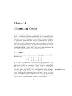
6 Data should have an odd number of 1'sA 1-bit parity code is a distance-2 code, in the sense that at least 2 bits must be changed (among the data and parity bits) produce an incorrect but legal pattern. In other words, any two legal patterns are separated by a distance of at least CorrectionError correcting codesprovide sufficient information to locate and correct some data must use more bits for state representation, 6 bits for every 32-bit data word- may indicate the existence of errors if up to kbits are wrong- may indicate how to correct the error if up to lbits are wrong, where l< k-ccode bits and ndata bits 2c>= n+ c+ 1We must have at least a distance-3code to accomplish Computer OrganizationComputer Science Dept Va Tech March 2006 2006 McQuain & RibbensWe must have at least a distance-3code to accomplish such a code, if we have a data word + error code sequence X that has 1 incorrect bit, then there will be a unique valid data word + error code sequence Y that is a distance of 1 from X.
7 And we can correct the error by replacing X with CorrectionA distance-3code is also knows as a single-error correcting, double-error detecting or X has 2 incorrect bits, then we will replace X with an incorrect (but valid) sequence. We cannot both detect 2-bit errors and correct 1-bit errors with a distance-3 , hopefully flipped bits will be a rare occurrence and so sequences with two or more flipped bits will have a negligible Computer OrganizationComputer Science Dept Va Tech March 2006 2006 McQuain & RibbensMemory15 hamming CodesRichard hamming described a method for generating minimum-length error-correcting codes. Here is the (7,4) hamming code for 4-Bit words:Data bits Check bits000000000010110010101001111001001100 1011010110011 Say we had the data word 0100and check bits two valid data words that match that check bit pattern would be 0001and latter would correspond to a single-bit error in Intro Computer OrganizationComputer Science Dept Va Tech March 2006 2006 McQuain & Ribbens011001101110001000111100110010100 1010110011100001110101011101001111111 The latter would correspond to a single-bit error in the data word, so we would choose that as the that if the error was in the check bits, we'd have to assume the data word was correct (or else we have an uncorrectable 2-bit error or worse).
8 In that case, the check bits would have to be 1 bit distance from 110, which they are Code DetailsHamming codes use extra parity bits, each reflecting the correct parity for a different subset of the bits of the code word. Parity bits are stored in positions corresponding to powers of 2 (positions 1, 2, 4, 8, etc.). The encoded data bits are stored in the remaining parity bits are defined as follows:- position 1: check 1 bit, skip 1 bit, check 1 bit, skip 1 bit, ..- position 2: check 2 bits, skip 2 bits, ..-position 2k: check 2kbits, skip 2kbits, ..Intro Computer OrganizationComputer Science Dept Va Tech March 2006 2006 McQuain & Ribbens-position 2k: check 2kbits, skip 2kbits, ..Consider the data byte: 10011010 Expand to allow room for the parity bits: _ _ 1 _ 001_1010 Now compute the parity bits as defined Code DetailsWe have the expanded sequence: _ _ 1 _ 0 0 1 _ 1 0 1 0 The parity bit in position 1 (first bit) would depend on the parity of the bits in positions 1, 3, 5, 7, etc:_ _ 1_ 0 0 1 _ 1 0 1 0 Those bits have even parity, so we have: 0_ 1 _ 0 0 1 _ 1 0 1 0 The parity bit in position 2 would depend on bits in positions 2, 3, 6, 7, etc:Intro Computer OrganizationComputer Science Dept Va Tech March 2006 2006 McQuain & RibbensThe parity bit in position 2 would depend on bits in positions 2, 3, 6, 7, etc:0_ 1_ 0 0 1_ 1 0 10 Those bits have odd parity, so we have: 0 11 _ 0 0 1 _ 1 0 1 0 Continuing, we obtain the encoded string: 0 11 10 0 1 01 0 1 0 Memory18 hamming Code CorrectionSuppose we receive the string.
9 0 11 10 0 1 01 1 1 0 How can we determine whether it's correct? Check the parity bits and see which, if any are incorrect. If they are all correct, we must assume the string is correct. Of course, it might contain so many errors that we can't even detect their occurrence, but in that case we have a communication channel that's so noisy that we cannot use it the parity bits above:Intro Computer OrganizationComputer Science Dept Va Tech March 2006 2006 McQuain & Ribbens0 1 1 1 0 0 1 0 1 1 1 0 OKWRONGWRONGOKSo, what does that tell us, aside from that the string is incorrect? Well, if we assume there's no more than one incorrect bit, we can say that because the incorrect parity bits are in positions 2 and 8, the incorrect bit must be in position 10.