Transcription of 4-Channel, 24-Bit Thermocouple Input Devices - daq.in
1 USER guide AND SPECIFICATIONSUSB-9211/9211A4- channel , 24-Bit Thermocouple Input DevicesThis user guide describes how to use the National Instruments USB-9211/9211A Devices and lists the .. 2 Safety Guidelines .. 2 Safety Guidelines for Hazardous Voltages .. 3 Software .. 3 Related 4 Installing the USB-9211/9211A Device .. 4 Installing the Software .. 4 Installing the NI USB-9211/9211A in the USB-9161/9162 Carrier .. 4 Mounting the USB-9211/9211A to a Panel .. 6 Connecting the USB-9211/9211A to a Computer .. 6 LED Indicator .. 6 Wiring the USB-9211/9211A.
2 7 Assembling the High Voltage Screw Terminal Backshell .. 8 USB-9211/9211A Circuitry .. 9 Effects of Source Impedance on Voltage Measurement Accuracy .. 9 Determining Temperature Measurement Accuracy and Minimizing 10 Using the Autozero 10 Measurement Accuracy for the Different Types of Thermocouples .. 11 Cold-Junction Temperature Measurement Accuracy .. 13 Minimizing Thermal Gradients .. 14 Specifications .. 14 Input Characteristics .. 14 Power Requirements .. 16 Bus Interface .. 16 USB-9211/9211A User guide and ..16 Standards ..17 Electromagnetic.
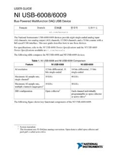
3 18 Where to Go for Support ..19 IntroductionThe NI USB-9211/9211A data acquisition device provides a USB interface for four channels of 24-Bit Thermocouple inputs with integrated signal conditioning. The NI USB-9211 consists of two components: an NI 9211 module and a USB-9161 carrier, as shown in Figure 1. The NI USB-9211A consists of two components: an NI 9211 module and a USB-9162 carrier, as shown in Figure 1. USB-9211/9211A ComponentsSafety GuidelinesOperate the USB-9211/9211A only as described in these operating Although the NI 9211 module may have more stringent certification standards than the USB-9211/9211A, when used with the USB-9161/9162 carrier, the combined system may be limited.
4 Refer to the Specifications section for more details. NI 9211 USB-9161/9162 USB-9211/9211A National Instruments Corporation3 USB-9211/9211A User guide and SpecificationsHot Surface This icon denotes that the component may be hot. Touching this component may result in bodily Do not disconnect I/O-side wires or connectors unless power has been switched off or the area is known to be Do not remove modules unless power has been switched off or the area is known to be The USB-9211/9211A is not certified for use in hazardous Guidelines for Hazardous VoltagesIf hazardous voltages are connected to the module, take the following precautions.
5 A hazardous voltage is a voltage greater than Vpk or 60 VDC to earth Ensure that hazardous voltage wiring is performed only by qualified personnel adhering to local electrical Do not mix hazardous voltage circuits and human-accessible circuits on the same Make sure that Devices and circuits connected to the module are properly insulated from human When module terminals are live with hazardous voltages, make sure that the terminals are not accessible by using the high voltage screw terminal enclosure. Refer to the Assembling the High Voltage Screw Terminal Backshell section for more support for your hardware depends on the carrier being used.
6 Refer to Table 1 for a list of software are included with each software API. Refer to the corresponding software getting started guide for more information. Table 1. Devices and Corresponding ComponentsDeviceCarrierSoftware SupportUSB-9211NI 9161NI-DAQmx BaseUSB-9211 ANI 9162NI-DAQmxUSB-9211/9211A User guide and DocumentationIf your device uses NI-DAQmx Base, refer to to download the the USB-9211/9211A DeviceInstalling the SoftwareBefore installing the device, you must install the software you plan to use with the device. Refer to the Software section of this manual and the documentation included with the software for more the NI USB-9211/9211A in the USB-9161/9162 CarrierThe NI 9211 module and the USB-9161/9162 carrier are packaged separately.
7 Refer to Figure 2, while completing the following assembly sure that no signals are connected to the NI 9211 module and the USB cable is not connected to the the protective cover from the 15-pin DSUB getting started GuideAccessible from Start All Programs National Instruments NI-DAQ after for USB Devices getting started GuideShips with your device and, after install, is accessible from Start All Programs National Instruments Base getting started GuideAccessible from Start All Programs National Instruments NI-DAQmx Bases Documentation after install.
8 National Instruments Corporation5 USB-9211/9211A User guide and the I/O module with the carrier, as shown in Figure 2. Module the latches and insert the NI 9211 module into the firmly on the connector side of the NI 9211 module until the latches lock the module into place, as shown in Figure 3. Locking Module into the USB cable to the assembled USB-9211 High Voltage Screw Terminal Backshell 1 USB-9211/9211A User guide and the USB-9211/9211A to a PanelThreaded inserts are located in the USB-9211/9211A for mounting it to a panel. Refer to Figure 4 for 4.
9 Module DimensionsConnecting the USB-9211/9211A to a ComputerPlug one end of the USB cable into the USB-9211/9211A and the other end into an available USB port on the IndicatorThe LED indicator indicates device 2. LED State/Device StatusLED StateDevice StatusNot litDevice not connected or in , not blinkingDevice connected, but no module error. Refer to Threaded InsertM3 x mm ( in.) Max mm( in.) mm( in.) mm( in.) National Instruments Corporation7 USB-9211/9211A User guide and SpecificationsWiring the USB-9211/9211 AThe USB-9211/9211A has a 10-terminal, detachable high voltage screw terminal enclosure that provides connections for four Thermocouple Input channels.
10 Each channel has a terminal to which you can connect the positive lead of the Thermocouple , TC+, and a terminal to which you can connect the negative lead of the Thermocouple , TC . The USB-9211/9211A also has a common terminal, COM, that is internally connected to the isolated ground reference of the The high voltage screw terminal backshell must be installed when using hazardous voltages (> Vpk, 60 VDC).If you are unsure which of the Thermocouple leads is positive and which is negative, check the Thermocouple documentation or the Thermocouple wire spool.