Transcription of 4. HVAC AND REFRIGERATION SYSTEM
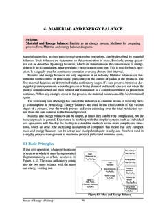
1 4. hvac AND REFRIGERATION SYSTEM71 Bureau of Energy EfficiencySyllabusHVAC and REFRIGERATION SYSTEM :Vapor compression REFRIGERATION cycle, Refrigerants,Coefficient of performance, Capacity, Factors affecting REFRIGERATION and Air conditioningsystem performance and savings absorption REFRIGERATION SYSTEM : Working principle, Types and comparison withvapor compression SYSTEM , Saving IntroductionThe Heating, Ventilation and Air Conditioning ( hvac ) and REFRIGERATION SYSTEM transfers theheat energy from or to the products, or building environment. Energy in form of electricity orheat is used to power mechanical equipment designed to transfer heat from a colder, low-ener-gy level to a warmer, high-energy deals with the transfer of heat from a low temperature level at the heatsource to a high temperature level at the heat sink by using a low boiling are several heat transfer loops in REFRIGERATION SYSTEM as described below:Figure Heat Transfer Loops In REFRIGERATION SystemIn the Figure , thermal energy moves from left to right as it is extracted from the space andexpelled into the outdoors through five loops of heat transfer: Indoor air the leftmost loop, indoor air is driven by the supply air fan through a cool-ing coil, where it transfers its heat to chilled water.
2 The cool air then cools the building space. Chilled water by the chilled water pump, water returns from the cooling coilto the chiller s evaporator to be re-cooled. Refrigerant loop. Using a phase-change refrigerant, the chiller s compressor pumps heatfrom the chilled water to the condenser water. Condenser water absorbs heat from the chiller s condenser, and the con-denser water pump sends it to the cooling tower. Cooling tower cooling tower s fan drives air across an open flow of the hotcondenser water, transferring the heat to the SystemsDepending on applications, there are several options / combinations, which are available for useas given below: Air Conditioning (for comfort / machine) Split air conditioners Fan coil units in a larger SYSTEM Air handling units in a larger systemRefrigeration Systems (for processes) Small capacity modular units of direct expansion type similar to domestic refrigerators,small capacity REFRIGERATION units.
3 Centralized chilled water plants with chilled water as a secondary coolant for temperaturerange over 5 C typically. They can also be used for ice bank formation. Brine plants, which use brines as lower temperature, secondary coolant, for typically subzero temperature applications, which come as modular unit capacities as well as large cen-tralized plant capacities. The plant capacities upto 50 TR are usually considered as small capacity, 50 250 TR asmedium capacity and over 250 TR as large capacity large industry may have a bank of such units, often with common chilled water pumps, con-denser water pumps, cooling towers, as an off site utility. The same industry may also have two or three levels of REFRIGERATION & air conditioning such as: Comfort air conditioning (20 25 C) Chilled water SYSTEM (8 10 C) Brine SYSTEM (sub-zero applications)Two principle types of REFRIGERATION plants found in industrial use are: Vapour CompressionRefrigeration (VCR) and Vapour Absorption REFRIGERATION (VAR).
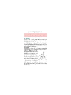
4 VCR uses mechanical ener-gy as the driving force for REFRIGERATION , while VAR uses thermal energy as the driving force Types of REFRIGERATION SYSTEM Vapour Compression REFRIGERATION Heat flows naturally from a hot to a colder body. In REFRIGERATION SYSTEM the opposite must heat flows from a cold to a hotter body. This is achieved by using a substance called a refrig-erant, which absorbs heat and hence boils or evaporates at a low pressure to form a gas. Thisgas is then compressed to a higher pressure, such that it transfers the heat it has gained to ambi-ent air or water and turns back (condenses) into a liquid. In this way heat is absorbed, orremoved, from a low temperature source and transferred to a higher temperature source. The REFRIGERATION cycle can be broken down into the following stages (see Figure ):1 2 Low pressure liquid refrigerant in the evaporator absorbs heat from its surroundings,usually air, water or some other process liquid.
5 During this process it changes its state from aliquid to a gas, and at the evaporator exit is slightly hvac and REFRIGERATION System72 Bureau of Energy Efficiency2 3 The superheated vapour enters the compressor where its pressure is raised. There willalso be a big increase in temperature, because a proportion of the energy input into the com-pression process is transferred to the 4 The high pressure superheated gas passes from the compressor into the condenser. Theinitial part of the cooling process (3 - 3a) desuperheats the gas before it is then turned back intoliquid (3a - 3b). The cooling for this process is usually achieved by using air or water. A furtherreduction in temperature happens in the pipe work and liquid receiver (3b - 4), so that the refrig-erant liquid is sub-cooled as it enters the expansion 1 The high-pressure sub-cooled liquid passes through the expansion device, which bothreduces its pressure and controls the flow into the hvac and REFRIGERATION System73 Bureau of Energy EfficiencyFigure : Schematic of a Basic Vapor Compression REFRIGERATION SystemIt can be seen that the condenser has to be capable of rejecting the combined heat inputs of theevaporator and the compressor; (1 2) + (2 3) has to be the same as (3 4).
6 There is noheat loss or gain through the expansion Refrigerants for Vapour Compression SystemsThe use of CFCs is now beginning to be phased out due to their damaging impact on the pro-tective tropospheric ozone layer around the earth. The Montreal Protocol of 1987 and thesubsequent Copenhagen agreement of 1992 mandate a reduction in the production of ozonedepleting Chlorinated Fluorocarbon (CFC) refrigerants in a phased manner, with an eventu-al stop to all production by the year 1996. In response, the REFRIGERATION industry has devel-oped two alternative refrigerants; one based on Hydrochloro Fluorocarbon (HCFC), andanother based on Hydro Fluorocarbon (HFC). The HCFCs have a 2 to 10% ozone depletingpotential as compared to CFCs and also, they have an atmospheric lifetime between 2 to 25years as compared to 100 or more years for CFCs (Brandt, 1992). However, even HCFCs4. hvac and REFRIGERATION System74 Bureau of Energy Efficiencyare mandated to be phased out by 2005, and only the chlorine free (zero ozone depletion)HFCs would be now, only one HFC based refrigerant, HFC 134a, has been developed.
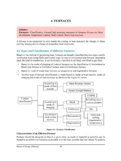
7 HCFCs arecomparatively simpler to produce and the three refrigerants 22, 123, and 124 have been devel-oped. The use of HFCs and HCFCs results in slightly lower efficiencies as compared to CFCs,but this may change with increasing efforts being made to replace RefrigerationThe absorption chiller is a machine, which produces chilled water by using heat such as steam,hot water, gas, oil etc. Chilled water is produced by the principle that liquid (refrigerant), whichevaporates at low temperature, absorbs heat from surrounding when it evaporates. Pure wateris used as refrigerant and lithium bromide solution is used as absorbentHeat for the vapour absorption REFRIGERATION SYSTEM can be provided by waste heat extract-ed from process, diesel generator sets etc. Absorption systems require electricity to run pumpsonly. Depending on the temperature required and the power cost, it may even be economical togenerate heat / steam to operate the absorption of the absorption REFRIGERATION concept is given below:The refrigerant (water) evaporates ataround 4 C under the high vacuum con-dition of 754mmHg in the the refrigerant (water) evaporates,the latent heat of vaporization takes theheat from incoming chilled water.
8 This latent heat of vaporization can coolthe chilled water which runs into the heatexchanger tubes in the evaporator bytransfer of heat to the refrigerant (water).In order to keep evaporating, therefrigerant vapor must be dischargedfrom the evaporator and refrigerant(water) must be supplied. The refriger-ant vapor is absorbed into lithium bro-mide solution which is convenient toabsorb the refrigerant vapor in theabsorber. The heat generated in theabsorption process is led out of systemby cooling water continually. Theabsorption also maintains the vacuuminside the hvac and REFRIGERATION System75 Bureau of Energy EfficiencyAs lithium bromide solution is diluted,the effect to absorb the refrigerantvapor reduces. In order to keepabsorption process, the diluted lithiumbromide solution must be madeconcentrated lithium bromide. Absorption chiller is provided with thesolution concentrating SYSTEM by theheating media such as steam, hotwater, gas, oil, which performs suchfunction is called concentrated solution flows intothe absorber and absorbs the refriger-ant vapor order to carryout above works con-tinually and to make complete cycle,the following two functions arerequired.
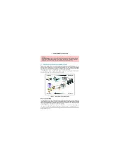
9 (1) To concentrate and liquefy theevaporated refrigerant vapor,which is generated in the highpressure generator.(2) To supply the condensed water tothe evaporator as refrigerant(water) For this function, condenser is typical schematic of the absorption REFRIGERATION SYSTEM is given in the Figure absorption REFRIGERATION systems have a Coefficient of Performance (COP) inthe range of and can provide chilled water at C with a cooling watertemperature of 30 C. Systems capable of providing chilled water at 3 C are also based systems operate at above atmospheric pressures and are capable of low tem-perature operation (below 0 C). Absorption machines of capacities in the range of 10 1500 tonsare available. Although the initial cost of absorption SYSTEM is higher than compression SYSTEM ,operational cost is much lower-if waste heat is CoolingThere are occasions where air conditioning, which stipulates control of humidity up to 50 % forhuman comfort or for process, can be replaced by a much cheaper and less energy intensiveevaporative concept is very simple and is the same as that used in a cooling tower.
10 Air is broughtin close contact with water to cool it to a temperature close to the wet bulb temperature. Thecool air can be used for comfort or process cooling. The disadvantage is that the air is rich inmoisture. Nevertheless, it is an extremely efficient means of cooling at very low cost. Largecommercial systems employ cellulose filled pads over which water is sprayed. The temperaturecan be controlled by controlling the airflow and the water circulation rate. The possibility ofevaporative cooling is especially attractive for comfort cooling in dry regions. This principle ispracticed in textile industries for certain Common Refrigerants and Properties A variety of refrigerants are used in vapor compression systems. The choice of fluid is deter-mined largely by the cooling temperature required. Commonly used refrigerants are in the fam-ily of chlorinated fluorocarbons (CFCs, also called Freons): R-11, R-12, R-21, R-22 and properties of these refrigerants are summarized in Table and the performance of theserefrigerants is given in Table hvac and REFRIGERATION System76 Bureau of Energy EfficiencyFigure Schematic of Absorption REFRIGERATION System4.