Transcription of 4 Lock the Incremental Encoder onto the Control Module ...
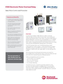
1 Installation InstructionsOriginal InstructionsPowerFlex 525 Incremental Encoder InputCatalog Number: 25-ENC-11L1L2L3OI2DC+ DC 0V0 VControl Module Back CoverIncremental Encoder InputWait three minutes after shutdown for capacitors to discharge to safe voltage DIP switchHTL/TTL DIP switchesNote: HTL/TTL DIP switch has two positions configured as HTL. The Voltage DIP switch 5V/12 selection is configured as the Incremental Encoder onto theControl Module Back CoverLock the Incremental Encoder onto theControl Module Back CoverMounting catchLocking tabNote: Incremental Encoder Input is for PowerFlex 525 can install both the communication adapter and optional Incremental Encoder Input on the same Control Module Back 520-IN009D-EN-P - May 2021 | Supersedes Publication 520-IN009-EN-P-July 2014 Copyright 2021 Rockwell Automation, Inc.
2 All rights reserved. Rockwell Otomasyon Ticaret A.. Kar Plaza Merkezi E Blok Kat:6 34752 erenk y, stanbul, Tel: +90 (216) 5698400 EEE Y netmeli ine Uygundur Allen-Bradley, expanding human possibility, FactoryTalk, PowerFlex, Rockwell Automation, and TechConnect are trademarks of Rockwell Automation, is a trademark of ODVA, not belonging to Rockwell Automation are property of their respective companies. 501262170325-ENC-1_2020-10 Your comments help us serve your documentation needs better. If you have any suggestions on how to improve our content, complete the form technical support, visit Electrical and Electronic Equipment (WEEE)
3 Rockwell Automation maintains current product environmental compliance information on its website at the end of life, this equipment should be collected separately from any unsorted municipal the Control Module Back CoverHow to Remove the Control Module Back Cover if RequiredIncremental Encoder Input with optional 25-COMM-D DeviceNet adapter shownIncremental Encoder Input label (pre-attached)Space for optional communication adapter label+VCmB-BA-A12V5V HTLTTL (ON)6No. SignalDescriptionAEncoder ASingle channel, pulse train or quadrature A A (NOT)BEncoder BQuadrature B B (NOT)CmPower ReturnInternal power source 250 mA (isolated).
4 + Power(1)(1)If Encoder requires 24V power, it must be supplied by an external power source OutputDIP switch selects 12 volt or 5 volt power that is supplied at terminals +V and Cm for the Encoder . HTL/TTL DIP switchesSet the position of the DIP switches based on the type of Encoder signal used. You must set all switches to the same ExampleI/OConnection ExampleEncoder Power Internal Drive PowerInternal (drive) 12V DC, 250 mAEncoder Power External Power SourceEncoder Signal Single-Ended, Dual ChannelEncoder Signal Differential, Dual ChannelCommon+12V DC(250 mA)AA-BB-Cm+Vto SHLD+CommonExternalPowerSupplytoSHLDA NOTABB NOTto SHLDto Power SupplyCommonAA-BB-Cm+Vto SHLDA NOTBAB NOTAA-BB-Cm+VWiring the Incremental EncoderMaximum Wire SizeMinimum Wire mm2 (14 AWG) mm2 (28 AWG) N m ( lb in)
5 Compatible Encoder Output VoltageSwitch PositionLow Level (UL)High Level (UH)TTL< > < >5V