Transcription of 4 SUBMERSIBLE PUMPS Two and Three Wire …
1 OWNERS MANUALINSTALLATION ANDOPERATING INSTRUCTIONS4& quot ; SUBMERSIBLE PUMPSTwo and Three WireSingle and Three Phase1/2 through 10 HzRecord the following information from the motor andpump nameplates for future reference:Pump Model Serial Model Serial Volts/Hz/PhRated Amp Draw 2006PN280(7/24/06)Carefully read and follow all safety instructions inthis manual or on is the you see thissymbol on your pump or in this manual,look for one of the following signal words and bealert to the potential for personal about hazards that willcauseserious personal injury, death or major propertydamage if about hazards that cancauseserious personal injury.
2 Death or major propertydamage if about hazards that willor cancause minor personal injury or property damage word NOTICE indicates special instructionswhich are important but not related to avoid serious or fatal personal injury and possi-ble property damage, carefully read and follow thesafety Hazardous pressure. Under cer-tain conditions, SUBMERSIBLE PUMPS can developextremely high pressure. Install a pressure reliefvalve capable of passing entire pump flow at 75 PSI (517 kPa) when using an air over water pres-sure tank. Install a pressure relief valve capableof passing entire pump flow at 100 PSI (690 kPa)when using a pre-charged pressure not allow pump, pressure tank, pip-ing, or any other system componentcontaining water to freeze.
3 Freezing maydamage system, leading to injury or pump or system components tofreeze will void voltage. Can shock,burn or cause death. To avoid dangerous or fatalelectric shock hazard, use pump only in a of dangerous or fatal not install this pump in any pond,river, orother open body of water that could be used forswimming or recreation. Do not swim, wade or playin a body of water in which a SUBMERSIBLE pump hasbeen must meet United StatesNational Electrical Code, CanadianElectrical Code, and local codes (as applicable)for all electrical power supply beforeinstalling or servicing sure line voltage and frequency ofpower supply match motor nameplate volt-age and Install pump according to all plumbing, pumpand well code Test well water for purity before using well.
4 Callyour local health department for testing During installation, keep well covered as muchas possible to prevent leaves and foreign matterfrom falling into well. Foreign objects in well cancontaminate the water and cause seriousmechanical damage to the Pipe joint compound can cause cracking in plas-tics. Use only teflon tape when sealing joints inplastic pipe or connecting pipe to OF CONTENTS Safety Instructions ..2 Pre-Installation ..2 Electrical ..2-18 PENTEK XE-Series ..4 PENTEK T-Series ..5-6 PENTEK 3-Phase ..7 Franklin ..8-11 Wiring.
5 12-18 Installation ..19-20 Initial Startup ..20-21 Effluent Applications ..21 Connecting to Tank/Water System ..21-23 Troubleshooting Guide ..24-25 Warranty ..26 PRE-INSTALLATIONI nspect pump and motor for delivery any damage immediately to the shippingcarrier or to your well driller should thoroughly develop the well(that is, pump out all fine sand and foreign matter)before pump is performance is based on pumping clear,cold, liquid is void in the following conditions: If pump has pumped excessive sand excessivesand can cause premature wear to pump.
6 If water is corrosive. If entrained gas or air are present in the waterbeing pumped these can reduce flow andcause cavitation which can damage pump. If pump has been operated with discharge valveclosed severe internal damage will pump at least 15 to 20' ( to 6 M) belowthe lowest water level reached with pump running(lowest draw-down water level), and at least 5'( ) above the bottom of the :Hazardous voltage. Can shock,burn, or cause death. Permanently ground pump,motor and control box before connecting powersupply to pump and motor in accordance with thelocal codes and ordinances.
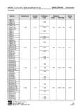
7 Use a copper groundwire at least as large as wires carrying current is supplied with a copper ground this ground wire to a copper conductorthat matches motor wire size specified in cable sizing charts,pages 5, 6, 10, and 11. SeePages 19 and 20 for cable splicing ground pump, motor and controlbox before connecting power cable to powersupply. Connect ground wire to approvedground first and then connect to equipmentbeing not ground to a gas supply and electrical shock hazard. Ifusing a drop cable larger than No. 10 ( )(for example, No. 8 ( ) wire) betweenpump and control box, run cable to a separatejunction box.
8 Connect junction box to controlbox with a No. 10 ( ) or smaller wire(depending on amp rating of pump see Table II,III, or IV).For more information, contact your local CONNECTIONS:Installation must meet United States NationalElectrical Code, Canadian Electrical Code andlocal codes for all wiring (as applicable).Use only copper wire when making connectionsto pump and control avoid over-heating wire and excessive voltagedrop at motor, be sure that wire size is at least aslarge as size listed in cable sizing charts for yourhorsepower pump and length of wire : See Pages 14 through 18 for typicalwiring hookups and control box : When built-in overheating protectionis notprovided, install an approved overloadequipped motor control that matches motorinput in full load amps.
9 Select or adjust overloadelement(s) in accordance with control instruc-tions. When built-in overheating protection isprovided, use an approved motor control thatmatches motor input in full load (3 Phase only)To make sure motor is running in the right direc-tion, proceed carefully as follows:After electrical connections have been made asoutlined, and with pump hanging in well sup-ported from clamp on the discharge pipe, turnon then turn off the switch connecting the motorto the power supply line. Note rotation of pumpas motor starts. If connections are properlymade, pump will jerk clockwise when lookinginto the pump discharge when started.
10 If jerk is counter-clockwise, the motor is running in thewrong direction. Interchange any two cableleads where they connect to the lead terminalsin the magnetic starter. With connections proper-ly made, and pump lowered into water, turn onthe switch again and the pump should deliverwater according to the performance PROTECTION OF THREEPHASE SUBMERSIBLE MOTORS CLASS 10 PROTECTION REQUIREDThe characteristics of SUBMERSIBLE motors aredifferent from standard motors and special over-load protection is the motor is stalled, the overload must tripwithin 10 seconds to protect the motor wind-ings.