Transcription of 40 Meter Mini-MOXON Beam Antenna At W7XA - IW5EDI
1 40 Meter Mini-MOXON Beam AntennaDesigned, built, and presented by:Al KoblinskiW7 XADesign goals Some forward gain Good directivity (high F/B and F/S ratios) Relatively small size Good Bandwidth (min. 200 KHz @ <2:1 SWR) Light weight Easy construction and tuning Low costSome current loaded 40M 2 El. beams Cushcraft (now owned by MFJ)o41 ft wingspanoInductive loaded with capacity hatsoAround $600oHygain (now owned by MFJ)o44 ft wingspanoLinear loadedo$660oForce 12 (240N)o58 ft wingspanoLinear loadedo$1700 !oMosley (multiband only)o44 ft wingspanoInductor loaded (with traps for higher bands)oPrice N/ANone of the commercial antennas mentioned met most of my goals Too big Too heavy Way too costly!Over the years there have been a lot of home brew and commercial mini-beams presented and none offer near full size of other schemes using loaded mobile antennas as beam elements such as the Buddipole , TGM B245 minibeam , etc.
2 None provide much if any gain All have low efficiency All have very narrow bandwidthBackgroundMy QTH is on a standard city lot about 90 X 110 feet. There is limited ground space in the back yard For radials etc. due to the swimming pool installed by the previous 2005, when returning to Arizona after a long absence and with limited time, I put up an old Cushcraft R7000 half wave vertical to get back on the air. Considering the lousy band conditions at the long bottom of the sunspot cycle, the R7000 proved to be a surprisingly good performer, especially on 40 2009 I acquired and installed a 55 ft. crank up tower and considered various antennas to put on had used cubical quads for many years and the decision for 20 meters and up was easy, but what to doFor 40 meters ?
3 Some years ago I built a MOXON Rectangle Antenna for 6 meters . The performance was excellent with good gain, great side and back rejection and seemed to work very well. Cost to build was very low and Construction was very not consider a MOXON or variant for 40 meters ?MOXON BackgroundSeveral designs emerged in the 1970s for reduced size beam antennas implemented by folding the elements. VK2 ABQ may have been the first to publish a design with his square Antenna . Similar antennas have been around since the 1930s. Elements were folded toward each other at about the 50% point (1/4 wave spacing required!!) Narrow Bandwidth Gain was relatively low F/B and F/S ratios were good. Design was fairly critical Antenna is a square configuration with equal size elements and a stub to lengthen the reflector.
4 Les Moxon G6XN discovered that a rectangular shape would improve the gain and lower the impedance Rectangular shape means shorter boom The tradeoff is a wider wingspan (about .35 wavelength) F/B and F/S rejection ratios remain excellent (Cardioid radiation pattern typical of phase arrays). good match to 50 ohm coax cable The only critical requirement is the tip-to-tip spacing Can be built with wire, tubing, or whatever Cebik W4 RNL (sk) has published a huge amount of data on the website about the MOXON and it s standard Moxon for 40 meters is about 46 feet wide and 18 feet long. An 18 ft. boom is doable and about the same as the quad that will share the boom (in my case) The 46 ft wingspan is wider than I 46 ft wingspan requires tubing elements to be reasonable self supporting, OR Lots of support halyards or guys, A large X frame to support an all wire MOXONFor me, these options are either too large, heavy, untidy, and would have high wind load cross the MOXON elements be loaded to reduce the size and maintain typical MOXON performance?
5 YES!Loading a MOXON has been shown to work well on the good example was the lumped inductor loaded MOXON designed and built by the MOXON Inductive loading, linear loading similar to the 402BA and other shortened yagis, helically loading, or capacity hat loading can reduce element length. Often a combination of these is hat loading is usually on or near the ends of the element for maximum effect and is not really practicalFor MOXON loop antennas. Since the coupling between the ends of the MOXON elements is critical this is not usually practical for reasons that will be presented loading is easiest and most practical. On a MOXON, the parallel elements are well supported or made from some kind of tubing and loading can be easily that most of the radiation on an Antenna is from the high current end of the elements (the end closest to the feedpoint in a dipole or wave vertical).
6 Lumped inductance: Usually done with a single coil inductor located somewhere along the element Close to the drive point (high current point on wave element) has the most shortening effect but is the least efficient position on the radiator. As the inductor is moved out toward the ends of the element, losses are less, Antenna efficiency is higher but the inductance needs to be progressively higher. Size and weight can become an lumped inductor approach was discarded for efficiency and weight the MOXON loading is very attractive for the MOXON design I had in loading is somewhat similar to lumped inductive loading but with the following advantages: Higher efficiency than a lumped inductor since the helix radiates in the normal mode and the lumpedInductor does not.
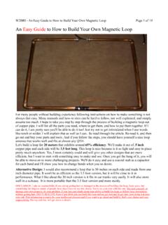
7 Weight is distributed along a wider length along the element. In the case of my MOXON, the helically wound portion is about half way from the center of the element including the end wires between the elements. Efficiency is very only downside for some is that the helix must be wound on an insulator. This is an advantage for my loading a beam or vertical has been extensively discussed in the ARRL Handbook, Antenna Handbook, Moxon s HF Antennas For All Locations for many, many let s proceed to the Mini-MOXON project at W7 XALinear loading (making a folded back section) is somewhat mechanically complex and can add significantly to the wind loading. This method was also MOXONThis set of dimensions was made by the MOXGEN utility downloadable from the web at no costTop viewfront The MOXGEN utility can calculate all wire or all tubing elements.
8 A mix of wire and tubing needs to done somewhat experimentally. If tubes are used for element A length and wire for B & D, then use the wire dimensions for B & D and adjust A for resonance. Dimension C is an insulator. I used Dacron (Phillistrand) MOXON chose 13 ft CUBEX (cubical quad) fiberglass spreaders for the 4 pieces that make up the 2 elements I have lots of them They are strong and good insulators suitable for winding the helical chose #8 Aluminum (electric fence) wire for the helically wound portion of the Antenna and the side wires Light weight Large diameter wire means high surface area (lower RF losses) Easy to use Solderable with Aluminum brazing rod and a torch Low purchased a mile of fence Aluminum fence wire for less than $150 I have found the wire to be as reliable as copper in most Antenna installations (including several Quads).
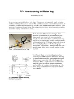
9 How much wire to use for the Helix portion?Most of the previously mentioned literature suggests that about wavelength of wire is needed for a Wavelength helix of the same the dimension A is 606 inches (50 ft), cut 4 pieces of wire about 70 feet the elementsStarting at the thin end of the spreader, secure one end of the wire to the spreader with a small hose clamp .(This is the hardest part!). Wind about 180 turns of the wire around the fiberglass spaced about inch turn to turn. Secure the inside wire with another hose turns should be as tight as possible on the fiberglass! The helix should take up about 7 feet of the spreader length. Not critical!Do not cut off the excess wire which should be about 8ft. or now your forearms should resemble Popeye s!
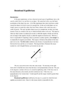
10 Set the elements build the center boom to element support for the wrapped to Boom ClampThe Cubex quad spreaders are 1 inch outside diameter. Other spreaders or insulating support tubes mayBe two 2 foot lengths of 1 inch inside diameter tube. I used heavy wall fiberglass tube available from Max-Gain Systems ( ) Aluminum tube is OK too but heavier. You will need four 2 inch U-bolts with saddles for each assembly. Two for each element support tube and two for the boom clamp (assuming a 2 inch boom). You will need two Aluminum plates, 3 X 12 inches, minimum 1/8 inch thickness (thicker is better up to inch). Push the spreaders 6 inches inside the support tube and use two self threading screws to secure the viewAluminum plateAssemble the elementsAfter the assembly of the spreaders to supports are completed do the following: Connect the inner wire lengths together Ideally raise the dipole to the top of a wooden stepladder as high as possible Check for resonance using a grid dipper.