Transcription of 400 MHz to 6 GHz Quadrature Demodulator Data Sheet …
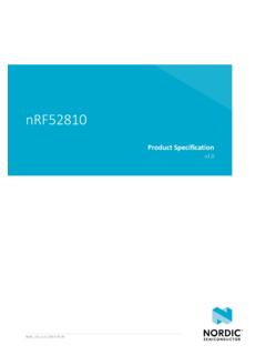
1 400 MHz to 6 GHz Quadrature Demodulator Data Sheet ADL5380 FEATURES Operating RF and LO frequency: 400 MHz to 6 GHz Input IP3 30 dBm at 900 MHz 28 dBm at 1900 MHz Input IP2: >65 dBm at 900 MHz Input P1dB (IP1dB): dBm at 900 MHz Noise figure (NF) dB at 900 MHz dB at 1900 MHz Voltage conversion gain: ~7 dB Quadrature demodulation accuracy at 900 MHz Phase accuracy: ~ Amplitude balance: ~ dB Demodulation bandwidth: ~390 MHz Baseband I/Q drive: 2 V p-p into 200 Single 5 V supply APPLICATIONS Cellular W-CDMA/GSM/ LT E Microwave point-to-(multi)point radios Broadband wireless and WiMAX FUNCTIONAL BLOCK DIAGRAM RFINRFIPENBLADJQUADRATUREPHASE SPLITTERADL5380V2 IBIASLOIPLOINIHIILOQHIQLO07585-001 Figure 1. GENERAL DESCRIPTION The ADL5380 is a broadband Quadrature I-Q Demodulator that covers an RF/IF input frequency range from 400 MHz to 6 GHz.
2 With a NF = dB, IP1dB = dBm, and IIP3 = dBm at 900 MHz, the ADL5380 Demodulator offers outstanding dynamic range suitable for the demanding infrastructure direct-conversion requirements. The differential RF inputs provide a well-behaved broadband input impedance of 50 and are best driven from a 1: 1 balun for optimum performance. Excellent demodulation accuracy is achieved with amplitude and phase balances of ~ dB and ~ , respectively. The demodulated in-phase (I) and Quadrature (Q) differential outputs are fully buffered and provide a voltage conversion gain of ~7 dB. The buffered baseband outputs are capable of driving a 2 V p-p differential signal into 200 . The fully balanced design minimizes effects from second-order distortion.
3 The leakage from the LO port to the RF port is < 50 dBm. Differential dc offsets at the I and Q outputs are typically <20 mV. Both of these factors contribute to the excellent IIP2 specification, which is >65 dBm. The ADL5380 operates off a single V to V supply. The supply current is adjustable by placing an external resistor from the ADJ pin to either the positive supply, VS, (to increase supply current and improve IIP3) or to ground (which decreases supply current at the expense of IIP3). The ADL5380 is fabricated using the Analog Devices, Inc., advanced silicon-germanium bipolar process and is available in a 24-lead exposed paddle LFCSP. Rev. B Document Feedback Information furnished by Analog Devices is believed to be accurate and reliable.
4 However, no responsibility is assumed by Analog Devices for its use, nor for any infringements of patents or other rights of third parties that may result from its use. Specifications subject to change without notice. No license is granted by implication or otherwise under any patent or patent rights of Analog Devices. Trademarks and registered trademarks are the property of their respective owners. One Technology Way, Box 9106, Norwood, MA 02062-9106, Tel: 2009 2014 Analog Devices, Inc. All rights reserved. Technical Support ADL5380 Data Sheet TABLE OF CONTENTS Features .. 1 Applications .. 1 Functional Block Diagram .. 1 General Description .. 1 Revision History .. 2 Specifications .. 3 Absolute Maximum Ratings.
5 5 ESD Caution .. 5 Pin Configuration and Function Descriptions .. 6 Typical Performance Characteristics .. 7 Low Band Operation .. 7 Midband Operation .. 11 High Band Operation .. 14 Distributions for fLO = 900 MHz .. 17 Distributions for fLO = 1900 MHz .. 18 Distributions for fLO = 2700 MHz .. 19 Distributions for fLO = 3600 MHz .. 20 Distributions for fLO = 5800 MHz .. 21 Circuit Description .. 22 LO Interface .. 22 V-to -I Converter .. 22 Mixers .. 22 Emitter Follower Buffers .. 22 Bias Circuit .. 22 Applications Information .. 23 Basic Connections .. 23 Power Supply .. 23 Local Oscillator and RF Inputs .. 24 Baseband Outputs .. 25 Error Vector Magnitude (EVM) Performance .. 25 Low IF Image Rejection .. 26 Example Baseband Interface.
6 27 Characterization Setups .. 31 Evaluation Board .. 33 Thermal Grounding and Evaluation Board Layout .. 35 Outline Dimensions .. 36 Ordering Guide .. 36 REVISION HISTORY 12/14 R e v. A t o R e v. B Changes to Figure 2 and Table 3 .. 6 Updated Outline Dimensions .. 36 Changes to Ordering Guide .. 36 7/13 R e v. 0 t o R e v. A Changes t o Ta b l e 2 .. 5 Deleted Local Oscillator (LO) Input Section .. 23 Changed RF Input Section to Local Oscillator and RF Inputs Section .. 24 Added Figure 78, Figure 79, and Figure 82, Renumbered Sequentially .. 24 Added Figure 83 and Figure 84 .. 25 Changes to Evaluation Board Section and Figure 102 .. 33 Changes to Table 5 and Figure 103 Caption .. 34 Deleted Figure 100, Figure 101, and Figure 102.
7 34 Updated Outline Dimensions .. 36 Changes to Ordering Guide .. 36 7/09 Revision 0: Initial Version Rev. B | Page 2 of 36 Data Sheet ADL5380 SPECIFICATIONS VS = 5 V, TA = 25 C, fLO = 900 MHz, fIF = MHz, PLO = 0 dBm, ZO = 50 , unless otherwise noted. Baseband outputs differentially loaded with 450 . Loss of the balun used to drive the RF port was de-embedded from these measurements. Table 1. Parameter Condition Min Typ Max Unit OPERATING CONDITIONS LO and RF Frequency Range 6 GHz LO INPUT LOIP, LOIN Input Return Loss LO driven differentially through a balun at 900 MHz 10 dB LO Input Level 6 0 +6 dBm I/Q BASEBAND OUTPUTS QHI, QLO, IHI, ILO Voltage Conversion Gain 450 differential load on I and Q outputs at 900 MHz dB 200 differential load on I and Q outputs at 900 MHz dB Demodulation Bandwidth 1 V p-p signal, 3 dB bandwidth 390 MHz Quadrature Phase Error At 900 MHz Degrees I/Q Amplitude Imbalance dB Output DC Offset (Differential) 0 dBm LO input at 900 MHz 10 mV Output Common Mode Dependent on ADJ pin setting VADJ ~ 4 V (set by k from ADJ pin to VS)
8 VS V VADJ ~ V (set by 200 from ADJ pin to VS) VS V VADJ ~ V (ADJ pin open) VS V dB Gain Flatness 37 MHz Output Swing Differential 200 load 2 V p-p Peak Output Current Each pin 12 mA POWER SUPPLIES VS = VCC1, VCC2, VCC3 Voltage V Current k from ADJ pin to VS; ENBL pin low 245 mA k from ADJ pin to VS; ENBL pin high 145 mA ENABLE FUNCTION Pin ENBL Off Isolation 70 dB Turn-On Settling Time ENBL high to low 45 ns Turn-Off Settling Time ENBL low to high 950 ns ENBL High Level (Logic 1) V ENBL Low Level (Logic 0) V DYNAMIC PERFORMANCE at RF = 900 MHz VADJ ~ 4 V (set by k from ADJ pin to VS) Conversion Gain dB Input P1dB dBm RF Input Return Loss R F I P, RFIN driven differentially through a balun 19 dB Second-Order Input Intercept (IIP2) 5 dBm each input tone 68 dBm Third-Order Input Intercept (IIP3)
9 5 dBm each input tone dBm LO to RF RFIN, RFIP terminated in 50 52 dBm RF to LO LOIN, LOIP terminated in 50 67 dBc IQ Magnitude Imbalance dB IQ Phase Imbalance Degrees Noise Figure dB Noise Figure Under Blocking Conditions With a 5 dBm input interferer 5 MHz away dB Rev. B | Page 3 of 36 ADL5380 Data Sheet Parameter Condition Min Typ Max Unit DYNAMIC PERFORMANCE at RF = 1900 MHz VADJ ~ 4 V (set by k from ADJ pin to VS) Conversion Gain dB Input P1dB dBm RF Input Return Loss R F I P, RFIN driven differentially through a balun 13 dB Second-Order Input Intercept (IIP2) 5 dBm each input tone 61 dBm Third-Order Input Intercept (IIP3) 5 dBm each input tone dBm LO to RF RFIN, RFIP terminated in 50 49 dBm RF to LO LOIN, LOIP terminated in 50 77 dBc IQ Magnitude Imbalance dB IQ Phase Imbalance Degrees Noise Figure dB Noise Figure Under Blocking Conditions With a 5 dBm input interferer 5 MHz away 14 dB DYNAMIC PERFORMANCE at RF = 2700 MHz VADJ ~ 4 V (set by k from ADJ pin to VS) Conversion Gain dB Input P1dB 11 dBm RF Input Return Loss R F I P, RFIN driven differentially through a balun 10 dB Second-Order Input Intercept (IIP2) 5 dBm each input tone 54 dBm Third-Order Input Intercept (IIP3)
10 5 dBm each input tone 28 dBm LO to RF RFIN, RFIP terminated in 50 49 dBm RF to LO LOIN, LOIP terminated in 50 73 dBc IQ Magnitude Imbalance dB IQ Phase Imbalance Degrees Noise Figure dB DYNAMIC PERFORMANCE at RF = 3600 MHz VADJ ~ V (set by200 from ADJ pin to VS) Conversion Gain dB Input P1dB dBm RF Input Return Loss R F I P, RFIN driven differentially through a balun 11 dB Second-Order Input Intercept (IIP2) 5 dBm each input tone 48 dBm Third-Order Input Intercept (IIP3) 5 dBm each input tone 21 dBm LO to RF RFIN, RFIP terminated in 50 46 dBm RF to LO LOIN, LOIP terminated in 50 72 dBc IQ Magnitude Imbalance dB IQ Phase Imbalance Degrees Noise Figure dB Noise Figure Under Blocking Conditions With a 5 dBm input interferer 5 MHz away dB DYNAMIC PERFORMANCE at RF = 5800 MHz VADJ ~ V (ADJ pin left open) Conversion Gain dB Input P1dB dBm RF Input Return Loss R F I P, RFIN driven differentially through a balun dB Second-Order Input Intercept (IIP2) 5 dBm each input tone 44 dBm Third-Order Input Intercept (IIP3)