Transcription of 400 Series 4-Wire Duct Smoke Detector 1-800-SENSOR2 (736 ...
1 Models AvailableDH400 ACDCI Ionization duct Smoke DetectorDH400 ACDCA Ionization Detector , ULC ListedDH400 ACDCP Photoelectronic duct Smoke Detector400 Series 4-Wire DuctSmoke Detector System Sensor 8/96 This document is not intended to be used for installation Division of Pittway3825 Ohio Avenue, St. Charles, IL 601741-800-SENSOR2 (736-7672), Fax 630-377-6495 inches (37 cm.)Width:5 inches ( cm.)Depth:4 inches ( cm.) lbs. ( kg.)OperatingTemperature Range:32 to 120 F (0 to 49 C)OperatingHumidity Range:10% to 93% relative humidityAir duct Velocity:500 to 4000 24 VAC/DC or 120/220 VAC operation Simple change-out of photo or ion Detector heads Air velocity rating from 500 to 4000 FPM Powered outputs for remote LED and sounder Remote test station option Remote sounder option Equipped with a DPDT auxiliary relay (two Form Ccontacts) Easy and quick mounting to round or rectangular ductsfrom 1 12 wide Clear cover for convenient visual inspection UL 268A listed 3-year warrantySystem Sensor DH400 ACDC 4-Wire duct housing willaccommodate either the 1451DH ionization sensor or the2451 photoelectronic sensor.
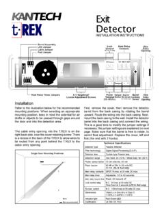
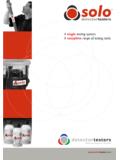
2 The twist-in, twist-outdetector heads allow easy removal for quick cleaning andmaintenance, or a change in application without removingthe duct housing. The DH400 ACDC samples air currentspassing through a duct and gives dependable performancefor management of fans, blowers, and air : duct Smoke detectors have specific detectors ARE:NOT a substitute for an open area Smoke Detector ,NOT a substitute for early warning detection, andNOT a replacement for a building s regular firedetection to NFPA 72 and 90A for additional duct detectorapplication 2A05-201-02 SAMPLING TUBEFILTERSCONDUIT HOLESDUCT Detector HOUSINGPC BOARD INSULATORDUCT DETECTORCOVERSAMPLING TUBEMOUNTINGSCREWSDETECTOR HEADEXHAUST FILTER ADAPTERDETECTOR BASEINLET SAMPLING TUBE(SUPPLIED SEPARATELY)O-RINGSFOAMGASKETSHOUSINGMOUN TING SCREWSTEST MAGNETTUBEENDPLUGE xploded View ofDH400 ACDC DuctDetector ComponentsArchitectural/Engineering SpecificationsThe air duct Smoke Detector shall be a System SensorModel DH400 ACDC Series duct Smoke Detector .
3 Thedetector housing shall be UL listed per UL 268 Aspecifically for use in air handling systems. The detectorshall operate at air velocities of 500 feet per minute to4000 feet per minute. The Detector housing shall beequipped with an integral mounting base capable ofaccommodating either photoelectronic or ionizationdetector heads. It shall be capable of local testing viamagnetic switch or remote testing using the RTS451 KEYR emote Test Station. The duct Detector housing shallincorporate an airtight Smoke chamber in compliance withUL 268A, Standard for Smoke detectors for DuctApplications. The housing shall be capable of mounting toeither rectangular or round ducts without adapterbrackets. An integral filter system shall be included toreduce dust and residue effects on Detector and housing,thereby reducing maintenance and servicing. Samplingtubes shall be installed after the housing is mounted to theduct by passing through the duct housing.
4 Terminalconnections shall be of the strip and clamp methodsuitable for 14 18 AWG Ratings DH400 ACDCP ower Supply Voltage20 - 29 VDC24 VAC 50 - 60 Hz120 VAC 50 - 60 Hz220/240 VAC 50 - 60 HzCURRENT REQUIREMENTS (USING NO ACCESSORIES)Max. standby current25 mA35 mA RMS20 mA RMS20 mA RMSMax. alarm current95 mA55 mA RMS55 mA RMS30 mA RMSCONTACT RATINGSA larm initiation contacts (SPST) @ 30 VAC/DC ( power factor)Alarm auxiliary contacts (DPDT)10A @ 30 VDC10A @ 277 VAC ( power factor)240 VA @ 240 VAC ( power factor)1/8 HP @ 120 VAC1/4 HP @ 240 VACT rouble contacts (SPST) @ 32 VDC (resistive)ACCESSORY CURRENT LOADS AT 24 VDCDEVICEAPA451PA400RA400 ZRTS451 KEYSTANDBY12mA MAX0mA0mA0mA*ALARM30mA MAX15mA MAX7mA MAX7mA MAX*ANY COMBINATION OF ACCESSORIES MAY BEUSED SUCH THAT THE GIVEN CURRENT LOADS TOTAL:100mA OR LESS IN THE STANDBY STATE,150mA OR LESS IN THE ALARM STATE.*NOTE: WHEN INITIATING AN ALARM, THE RTS451 REQUIRES 71mA MAXIMUM IN PRE-ALARMAND 78mA MAXIMUM IN ALARM.
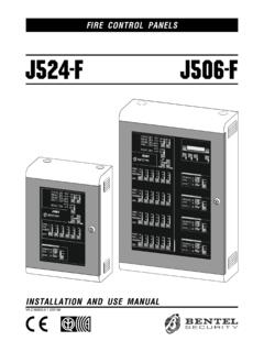
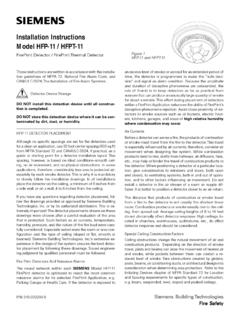
5 NOMINALSTANDBY CURRENT IS 0mA. ALARM CURRENTIS 7mA MAXIMUM WHEN TEST MAGNET 3A05-201-02DH400 ACDC Wiring GuideCAUTION: Do not loop wire under wire run to provide supervision of Diagram forDH400 ACDC 4-Wire DuctDetector System EquippedWithout a Control Panel24V120 VAC220/240 VAC12121314 AVAILABLE POWER INPUTSALARM AUXILIARY CONTACTSFOR FAN SHUTDOWN, AUXILIARY CONTACTS SHOWN INSTANDBY. CONTACTS TRANSFER DURINGALARM AS INDICATED BY THE INITIATION CONTACTSTROUBLE CONTACTS CLOSED IN ALARM AND OPEN WHILE Detector HEAD OR POWER ISREMOVED, AND DURING RESET. OPEN CONTACTSSIGNAL TROUBLE CONDITION TO (+) ALARM SIGNALAUDIBLE PIEZO ALERT WITH ALARM ANDPOWER (TROUBLE) LEDS. FOR STAND ALONEAPPLICATIONS ONLY. APA451 RECOMMENDEDFOR COMPLIANCE TO NFPA 90A. LOCATE INNORMALLY OCCUPIED AREA OF DETECTORSEE SPECIFICATIONS FORADDITIONAL POWERSUPPLY WIRING OF AUXILIARYDEVICES, REFER TOMANUFACTURER SINSTALLATION INSTRUCTIONSOR CONTACT MANUFACTURER.
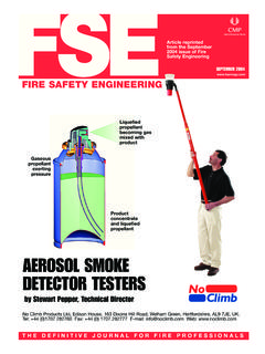
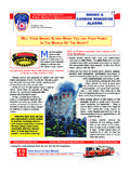
6 ( ) AUX POWER(+) AUX POWER INPUTSALARM AUXILIARY CONTACTSFOR FAN SHUTDOWN, AUXILIARY CONTACTS SHOWN INSTANDBY. CONTACTS TRANSFER DURINGALARM AS INDICATED BY THE CONTACTSTROUBLE CONTACTS CLOSED IN ALARM AND OPEN WHILE Detector HEAD OR POWER ISREMOVED, AND DURING RESET. OPEN CONTACTSSIGNAL TROUBLE CONDITION TO POWER INPUTSALARM AUXILIARY CONTACTSFOR FAN SHUTDOWN, AUXILIARY CONTACTS SHOWN INSTANDBY. CONTACTS TRANSFER DURINGALARM AS INDICATED BY THE CONTACTSTROUBLE CONTACTS CLOSED IN ALARM AND OPEN WHILE Detector HEAD OR POWER ISREMOVED, AND DURING RESET. OPEN CONTACTSSIGNAL TROUBLE CONDITION TO SHOWNOPEN IN CLOSEIN SHOWNOPEN IN CLOSEIN LISTED FIRE ALARMCONTROL PANELFIRST Detector IN THE LOOPDH400 ACDCLAST Detector IN THE LOOPDH400 ACDCEOL RESISTORSPECIFIED BYPANEL MANUFACTURERCONNECT POWER SOURCETO APPROPRIATE TERMINALSOF EACH Detector . SEESPECIFICATIONS FORADDITIONAL POWER WIRING OF AUXILIARYDEVICES, REFER TOMANUFACTURER'SINSTALLATION INSTRUCTIONSOR CONTACT Wiring Diagramfor DH400 ACDC 4-WireDuct Smoke DetectorsUsing a UL Listed ControlPanelWiring Diagrams forOptional AccessoriesALARM SIGNAL (+)AUX POWER ( )56(+)( ) duct DETECTORDH400 ACDCPA400 (OPTIONAL)AUDIBLE ALERTALARM SIGNAL (+)AUX POWER ( )56(+)( ) duct DETECTORDH400 ACDCRA400Z (OPTIONAL)REMOTE (LED)ANNUNCIATORALARM SIGNAL (+)AUX POWER ( )5612 duct DETECTORDH400 ACDCRTS451(OPTIONAL)REMOTE TESTSTATION5343 RESETTEST4 FIELDINSTALLEDJUMPERRESET ( )TEST ( )5634 ALARM (+)AUX POWER ( )RESET ( )TEST ( )712435 RESETTEST6DH400 ACDC duct Smoke DetectorRTS451 KEY Remote Test StationSIGNALAUX POWER (+)
7 SUPERVISORYCONTACTS1110{Page 4A05-201-02 APA451 Annunciator withPiezo Alarm and Power LEDsRTS451 Remote Test StationOrdering InformationPart ionization duct detectorDH400 ACDCASame as above, Canadian modelDH400 ACDCP4- wire photoelectronic duct detector1451 DHReplacement ionization sensor head2451 Replacement photoelectronic sensor sampling tube duct widths 1 2 ST-3 Metal sampling tube duct widths 2 4 ST-5 Metal sampling tube duct widths 4 8 ST-10 Metal sampling tube duct widths 8 12 APA451 Annunciator with piezo alarm and power LEDs(see below)RTS451 Remote test stationRTS451 KEYR emote test station with key (see below)MOD400 RSensitivity test modulePA400 Piezo sounderRA400 ZRemote annunciator alarm LEDCRT400 Ion cover removal toolF36-05-00 Replacement air filters (two per package)M02-04-00 Test magnetP48-21-00 End cap for metal sampling tubesRS14 Ion replacement screenRS24 Photo replacement screenR59-18-00 Calibrated test card (for photo units only)A2650-01 Replacement installation kit (mountinghardware)System Sensor Worldwide DistributionIn Canada:System Sensor Canada6581 Kitimat Road, Unit #7 Mississauga, OntarioCanada L5N 3T5 Telephone: 905-812-0767 Fax: 905-812-0771In the United Kingdom:System Sensor Europe, Gates III, North , West SussexRH13 5PJ, United KingdomTelephone: 44-1403-276500 Fax: 44-1403-276501In India:System Sensor IndiaA-204 Maheshwari NagarOrkay Mills LaneAndheri East, Mumbai 400093 Telefax: 91-022-8202564In the Far East:System SensorPittway Far East, 706, New T&T Centre7 Canton RoadTsimshatsui, Kowloon, Hong KongTelephone: 852-2730-9090 Fax: 852-2736-6580}