Transcription of 433 MHz Receiver & Transmitter Installation Instructions
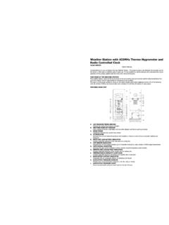
1 MHz Receiver & Transmitter Installation Instructions21 SystemThe Larco ultra-small Receiver and transmitters operate at MHz (acceptable in the United States, Canada and any European Union member state) and employ code-hopping technology to reduce false activations. The Receiver only operates after learning a Transmitter s signal through the simple procedure outlined on the next page. This programming procedure eliminates the need to set dip switches and involves a simple press of the programming button located on the top cover of the Receiver (see Diagram 1).NOTE: Read this document in its entirety before installing any Larco Transmitter or Receiver . It is important to complete the programming procedure before installing the Receiver in its final location. The installer must have access to the Receiver s programming button and must be able to view the Receiver s LED (Light Emitting Diode) during the programming the Receiver in a location so that the antenna is not surrounded by metal.
2 Metal attenuates RF signals causing a reduction in range and inconsistency of signal reception. Door operator motors and controls may also cause radio frequency interference. Locate the Receiver away from the door control s motor and power supply. If the Receiver is mounted in a metal enclosure, drill a hole in the enclosure and thread as much of the antenna as possible through the hole. This reduces the effects the metal enclosure will have on the Receiver s Receiver comes equipped with a wiring harness for easy Installation . Reference the wiring diagram (see Diagram 2) for proper the programming procedure before placing the Receiver in final location. The Receiver and Transmitter comply with FCC part 15 , Industry Canada RSS-210, EN55022A, EN55024, EN300-220-3, and EN301-489-1.
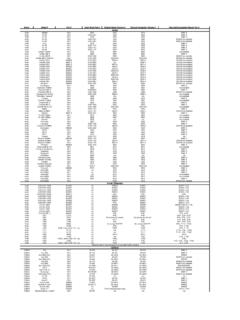
3 Operation is subject to the following two conditions: (1) This device may not cause harmful interference, and (2) this device must accept any inerference received, including interference that may cause undesired operation. This product may be susceptible to local transmissions being generated near the Transmitter s fundamental frequency. Testing has shown some susceptibility in a frequency range of 416-440 1: Receiver and Transmitter DimensionsDiagram 2: Receiver Wiring Harness Orange: Relay Output Normally Open Brown with White Stripe: Relay Output Common Red: 24 VAC/24 VDC Power Black: Ground Purple : 12 VAC/12 VDC Power Brown: Relay Output Common Yellow: Relay Output Normally ClosedOutput Common24 VAC/24 VDCGND12 VAC/12 VDC Power Output CommonOutput in. / 152 mmReceiver TerminalsLEDRECEIVERB uttonTransmitter Item # 234475 Receiver Item # 233804 Hotron Dublin Street, Carlow, Ireland.
4 TEL: +353 (0)59 914 0345 FAX: +353 (0)59 914 0543 Email: Rev. D 5/1521 Program the Transmitter into the Receiver s Receiver can learn up to 12 transmitters. Follow the steps below to program Receiver . Repeat steps A-C for each Transmitter . A. Press and release the Receiver s programming button. The LED should change from flashing red to solid green. This indicates the Receiver has entered its programming mode. B. Activate and release the Transmitter once and confirm that the Receiver s LED changes to solid red. This indicates the Receiver is learning the Transmitter s code. C. Wait a few seconds and then activate the Transmitter a second time. The Receiver s LED should now flash green several times. This indicates the end of the learning procedure. When the procedure has ended, the LED should be flashing the Receiver s output activation the Receiver is activated, its outputs will stay in the minimum activation state for approximately seconds (default).
5 This time can be adjusted to stay in the activation state for up to 4 hours. Follow the steps below to adjust the Receiver s outputactivation time. A. Press and hold the Receiver s programming button for 6 seconds and release. The LED should be solid red. This indicates the Receiver is in the activation time programming mode. B. Activate and release the Transmitter . C. When the desired time has elapsed (up to 4 hours) activate the Transmitter again. The Receiver s LED should flash green several times. This indicates the end of the procedure. When the procedure has ended, the LED should be flashing ProceduresPrior to programming, make sure the Receiver s LED flashes red when power is applied. If the Receiver s LED is not flashing red, disconnect then reconnect the all Transmitters from the Receiver s MemoryThe Receiver s memory can be cleared of all previously learned transmitters by following the steps below.
6 NOTE: Deleting previously learned transmitters does not change the Receiver s output activation Press and hold the Receiver s programming button for more than 8 seconds, until the Receiver s LED starts flashing green. Release the programming button. The LED should now be flashing The Receiver s memory is now cleared. To learn new transmitters, follow the steps for programming transmitters into the Receiver s specificationsreceiver item # x x Security Code MethodCode Hopping - Can Learn up to 12 Different TransmittersOperating Temperature Range-4 F to 122 F (-20 C to 55 C)Electrical Rating100,000 Cycles @ 2 Amps at Either 24 VDC or 120 VACI nput Power24 VAC/VDC or 12 VAC/DCOutputTwo Relay Outputs: 1 NO 1 NCCertificationsFCC, Industry Canada, CEtransmitter item # x x Security Code MethodCode HoppingBattery Life60,000 CyclesCertificationsFCC, Industry Canada, CEOperating Temperature Range-4 F to 122 F (-20 C to 55 C)433 MHz Receiver & Transmitter Installation Instructions (cont.)
7