Transcription of 4573 Electric actuators SQS35 SQS85
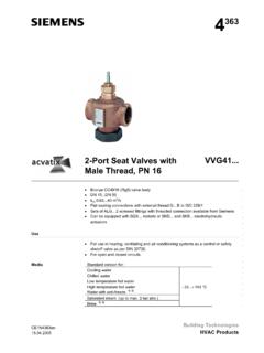
1 Siemens Building TechnologiesCM1N4573E / & Staefa Division1/84573 Electric actuatorsfor valves witha mm , , , SQS65, , spring return / without manual adjustmentwithout spring return / with manual adjustmentElectric actuators AC 230 V operating voltage, 3-position control signal 24 V operating voltage, 3-position control signal AC 24 V operating voltage, DC 0 ..10 V or DC 2 .. 10 V control signal Positioning force 400 N Stroke mm For direct mounting on valves, without adjustment Optional auxiliary switch for additional functions with , , and Choice of actuatorswithorwithoutspring return function to DIN 32 730 Non-spring return actuatorswithposition indication andwithmanualadjustment Spring return actuatorswithposition indication andwithoutmanualadjustmentUsed to operate 2-port and 3-port valves with a mm stroke. For valve types , , , , , , , , Area of application in accordance with IEC 721-3-3 Class 3K5 Ambient temperatures: 5.
2 +50 C Temperature of medium in the connected valve:+ 2 ..+ 130 C The use of mounting kit ASK30 enables the following valves with a 4mm or mmstroke to be operated: , , , and reversible synchronous motor is driven with a 3-position control signal ( ) or a proportional DC V (SQS65, ) or DC V( ) control signal. The corresponding stroke is generated via an anti-lockinggear control at terminals Y1 or Y2: Voltage at Y1:Valve stem retracts, through-port opens Voltage at Y2:Valve stem extends, through-port closes No voltage at Y1 or Y2: Valve stem holds current positionApplicationFunctions3-position or proportionalcontrol signalCM1N4573E / Building Technologies2/8 Landis & Staefa DivisionConnector S1 (under the cover, on the printed circuit board) can be repositioned tochange the flow characteristic of valves with a mm stroke from equal percentage to linear ; in all cases the flow characteristic relates to the through-port of the valve.
3 Connecting S1 to pins A and C produces anequal percentageflow characteristic(factory setting), primarily for heating applications Connecting S1 to pins B and C produces alinearflow characteristic,primarily for cooling applications For automatic operation, S1 must be connected either to pins A and C, or B and C,depending on the required flow connected to:AandC(equal-percentage flow characteristic)S1 connected to:CandB(linear flow characteristic) , ~ , ~CBRelationship between the DC Vor DC V control signal and thevolumetric flow rateControl signals:Y=DC 0 ..10 V or DC Flow characteristiclog=Equal-percentage valve characteristic(factory setting)lin=Linear valve characteristicFlow rangek&V100=Volumetric flow 100%k&V0=Volumetric flow 0 %Volumetric flow ratelinlog4573D01kV100kV00V2V10 V10 VControl-signalTypeOperatingvoltageType of control(Control signal)Run-time[s]Spring-returnfunctionS pring-return time[s] 230 24 VDC actuatorsSpace forAuxiliary , , x ordering, please specify the quantity, product name, type, and any :1 actuator , type auxiliary switch type actuator , valve and accessories are packed separately and not assembled prior the flowcharacteristicPosition of S1 Flow characteristicTypesAccessoriesOrderingDe liverySiemens Building TechnologiesCM1N4573E / & Staefa Division3/8 The following mm stroke, threaded two-port and three-port valves can be operatedwith Electric actuator types , and [mm]PN[bar]Data sheetTwo-port.
4 (2)15, (2)15, .. , 2016N4841 Three-port valves with bypass "T" .. (4)15, (4)15, 2016N4844 The admissible differential pressure values pmaxand psfor the complete motorised valve are shown inthe relevant valve data sheets. Electric actuator , no maintenance required Reversible synchronous motor Anti-locking gear mechanism , , have spring return function to DIN 32730 Load-dependent switch-off in stroke limit positions Selectable flow characteristic:equal percentage or linear for inconjunction with valve types , and Directly impacting manual adjustment for all non-spring-return actuators : , , SQS65, , Position indicator on all , , actuators Accommodation for auxiliary switch type on the , , and actuators . An auxiliary switch (notthe ) is built inas standard in actuator types and , , adjustment2 Position indication3 Coupling bolt for valve neck67501163 UMRYGG0R- MACBS167501163 UMRYGG0R- , strip6 Auxiliary switch built-in as standard and strip6 lin / log connection7 BridgeR MCompatibilityMechanical designManual adjustmentTerminal strip, auxiliaryswitch / Building Technologies4/8 Landis & Staefa auxiliary switchSuitable for actuator types , , and point adjustable from strokeSee Technical data for further information onaccessories4573Z04 The actuator must be dismantled and separated into its various constituent materialsbefore actuators must be electrically connected in accordance with local regulations andwith the connection and requirements to ensure the safety of people and property mustbe observed at all the actuators .
5 The connector used to select the flow characteristicmust be set to lin for valve types , , and admissible temperatures (see Application and Technical data )mustbeobserved. If an auxiliary switch is required, its switching point must be indicated on theplant permissibleInstructions for fitting the actuator to the valve are shown on the back of the actuatorhousing. The instructions for accessories are enclosed with the commissioning the system, check the wiring and functions. In addition, set theauxiliary switch or check the 0 = Valve closedStroke I = Valve openManual adjusterTurning the manual adjuster in an anti-clockwise direction causesLandis & Staefa valves with a mm stroke to close (= 0% stroke). Building TechnologiesCM1N4573E / & Staefa Division5/8 Used in conjunction with valve types , or , these actuatorsgenerate a linear flow conjunction with valve types , or these actuators generatean equal-percentage flow characteristic (factory-setting) via the integrated electronicassembly.
6 The flow characteristic can be changed to linear by repositioning technical data ( pmax, ps, leakage rates, noise levels, service life etc.) given for theapplications described applies only to the Landis & Staefa valves listed in this datasheet under Compatibility .The use of type in conjunction with third-party valves invalidatesall claims under the Landis & Staefa servicing the valve: switch OFF the pump and power supply, close the main shut-off valve in the pipework, release pressure in the pipes and allow them to cool downcompletely. If necessary, disconnect electrical connections from actuator must be correctly fitted to the valve before 230 V 15 % , 50 / 60 24 V 20 % , 50 / 60 24 V 20 % , 50 / 60 HzPower VASQS65, VASwitching capacity of limit switchesTerminals 11 or , 250 V, 6 A resistive / A inductiveType of control (control signal) , V (proportional) V (proportional)Run-timeOpening or , , s at 50 , , s at 50 HzSQS65, , s at 50 HzSpring return , , time 8 sPositioning force400 mmTerminal Y (SQS65, )DC 0.
7 10 V, max. mATerminal Y ( )DC 2 .. 10 V, max. mATerminal R (SQS65, , )Resistance 0 ..1000 Terminal U (SQS65, , )DC 0 ..10 V, max. mAHousing protection standardIP54 to EN 60529 Cable glandsPg11 (2 x)Temperature of medium in the connected valve+2 .. +130 / dataPower supplyOperating dataSignal inputsSignal outputsHousing protection standardAmbient conditionsCM1N4573E / Building Technologies6/8 Landis & Staefa DivisionOperationTo IEC 721-3-3 Environmental conditionsClass 3K5 Temperature 5 ..+50 95 %rhTransportTo IEC 721-2-3 Environmental conditionsClass 2K3 Temperature 25 ..+70 CHumidity< 95 %rhStorageTo IEC 721-1-3 Environmental conditionsClass 1K3 Temperature 5 ..+50 CHumidity5 .. 95 %rhMeets the requirements forCEmarking:EMC Directive89/336/EECLow Voltage Directive73/23/EECD imensionsSee Dimensions , , SQS65, , , kgWith , , kgWith kgActuator housingPlasticsHousing cover and manual adjusterPlasticsGear train and stem with switch for capacityAC 250 V, 10 A resistive / 3 A inductive M4573G01Y13Y2100%0%1112NL45Cm1Cm2c1 21Y1Y2H4NM100%0%max.
8 50%0% , 230 V, 3-position, non-spring returnCm1 Limit switch 100 % strokeCm2 Limit switch 0 % auxiliary switch can be fittedLVolt-free loop terminal for live , 230 V, 3-position, with spring returnc2 Built-in auxiliary switch with fixed presetminimum flow limit control.(Factory-fitted, not accessory like ) M90190Y13Y2100%0% , 24 V, 3-position, non-spring returnCm1 Limit switch 100 % strokeCm2 Limit switch 0 % auxiliary switch can be fittedLVolt-free loop terminal for live wireIndustry standardsDimensions / Building TechnologiesCM1N4573E / & Staefa Division7/8 Connection , G0 Operating voltage AC 24 VGSystem potential (SP) corresponds to LS on System neutral (SN) corresponds to NS on inputsYSQS65, VRSQS65, , ..1000 ohmsMMeasuring neutralUSignal outputSQS65, , VAll connection options are illustrated in the connection diagrams. How many and whichof these are used, depends on the a device is connected to terminal R, the factory-fitted bridge across R Montheprinted circuit board must be cut (1,2,3)RMMRG0 YGY(Y') R MUGOAC 24 VN1R1F1K1P1Y14573A01 GSPSNLSNSY (1,3)RMGYG0 RMMRUG0YG4573A02AC 24 VN1R1F1P1K1Y1 EquipmentF1 Frost detectorK1On/off switchN1 CLASSIC controllerP1 Position indicatorR1 Position transmitterK1On/off switchN1 CLASSIC controllerP1 Position indicatorR1 Position transmitterY1 ActuatorConnectiondiagramsNoteSQS65, (AC 24 V, DC 0.)
9 10 V) (AC 24 V, DC 2 ..10 V)CM1N4573E / Building Technologies8/8 Landis & Staefa DivisionAll dimensions in mm60681282888120134G "8032111* 18,5(Pg 11)4573M01*Height of actuator after fitting on valve> 100 mmMinimum clearance from wall or ceiling> 200 mmfor mounting, connection, operation, service 2000 Siemens Building Technologies to changes