Transcription of 4677 LDT-1002 & LDT1002GY 10 Cu. Ft. Dump Cart
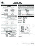
1 4677. LDT-1002 & LDT1002GY . 10 cu . Ft. dump Cart 05/05. ASSEMBLY INSTRUCTIONS Parts List for the LDT-1002 & LDT1002GY . Ref. Parts Description Qty Ref. Parts Description Qty No No No No 1 4562B Body (Black) 1 10 1262 Cotter Pin 2. **Painted parts have ** 4562GY Body (Gray) 11 1264 3/4 Flat Washer 4. two part numbers 2 4631B Tow Bar (Black) 1 12 4468 1/4 x 2-3/4 Spacer 1. due to the two ** 4631GY Tow Bar (Gray) 13 1586 5/16 x 3/4 Truss Hd Bolt 4. available colors for this model. 3 4560B Tailgate (Black) 1 14 4497 Spring 1. ** 4560GY Tailgate (Gray) 15 4552 3/8 x 3/4 Truss Head Bolt 8. 4 4630B Pedestal (Black) 1 16 1273 3/8 Hex Head Nut 8. Tools Needed For Cart Assembly: ** 4630GY Pedestal (Gray) 17 1248 5/16 x 3/4 Hex Head Bolt 2.
2 5 4556B Undercarriage (Black) 1 18 1275 5/16 Hex Head Nut 6. Two - 7/16 Wrenches ** 4556GY Undercarriage (Gray) 19 1274 3/8 Lock Washer 8. Two - 1/2 Wrenches 6 1243P Clevis (Black) 1 20 1276 5/16 Lock Washer 6. One - 9/16 Wrench ** 1243GY Clevis (Gray) 21 4466 1/4 x 3-1/2 HH Bolt 1. One - Pair Pliers 7 1265P Latch (Black) 1 22 1558 1/4 Lock Nut 1. One - Large Flat Blade Screw Driver ** 1265GY Latch (Gray) 23 1817 1/4 Flat Washer 2. 8 1252 Axle 1 24 1840 1/2 x 1-3/4 Clevis Pin 1. 9 4559 Wheel 2 25 1042 #14 Hitch Pin Clip 1. 1.) Insert 1/4 Spacer (12) through Spring (14) and 5/16 Hex 1/4 Flat 1/4 x 3-1/2 . the hole at bottom of Latch (7). Be sure Spring is #14 Hitch Head Nuts Hex Head Bolt Washer attached to Latch as shown.
3 Push Latch down through Pin Clip slot in Tow Bar (2) as shown. NOTE: Grab the Latch Handle from the other side of the Tow Bar and Latch 1/4 x 2-3/4 . pull down to align the Spacer with the holes in Spacer 5/16 Lock the sides of the Tow Bar. Slide 1/4 x 3-1/2 Bolt (21). Clevis Washers through side of Tow Bar, Washer (23), Spacer, Spring Washer (23), and other side of Tow Bar. Secure with 1/4 Lock Nut (22). Attach the Clevis (6) to the Tow Bar using 1/4 Flat 5/16 x 3/4 Hex Head Bolts (17) , 5/16 Lock Washer Washers (20) and 5/16 Hex Head Nuts (18). 1/2 x 1-3/4 Tow Bar Insert the 1/2 x 1-3/4 Clevis Pin (24) Clevis Pin 5/16 x 3/4 . through the large hole in the Clevis and Tow Bar. Hex Head Bolts 1/4 Reverse Secure the Clevis Pin by inserting the #14 Hitch Lock Nut Pin Clip (25) through the small hole on the end.
4 2.) Attach Undercarriage Axle Support (5) on bottom of 3/8 Lock 3/8 Hex Undercarriage Washer Head Nut Body (1). Use 3/8 x 3/4 Truss Head Bolts (15), Axle Support 3/8 Lock Washers (19), and secure with 3/8 Hex Head Nuts (16). 5/16 Hex Bolt the Pedestal (4) at front of Body with Head Nut 5/16 x 3/4 Truss Head Bolts (13) from inside. On the outside, use 5/16 Lock Washers (20) 5/16 Lock and secure with 5/16 Hex Head Nuts (18). Washer Pedestal 3/8 Hex Head Nut 3/8 Lock Washer Body 3/8 x 3/4 Truss 5/16 x 3/4 Truss Head Bolts Head Bolt LDT1002 & LDT1002GY ASSEMBLY INSTRUCTIONS Continued 3.) Slide the Axle (8) halfway through the Undercarriage Axle Support. Next, insert the Axle through both holes in the end of the Tow Bar and on through the other side of the Undercarriage Axle Support.
5 Connect the Tow Slide Axle through Undercarriage Wheel Bar to the Pedestal using the Tow Bar Latch. Tow Bar Axle Place a 3/4 Flat Washer (11) over the Axle up Latch against the Undercarriage Axle Support. Next, place a Wheel (9) onto the Axle. Place another 3/4 Flat Washer (11) over the Axle and secure the Wheel into place by inserting the Cotter Pin (10) through the hole in the end the Axle and spreading the legs of the Cotter Pin Pedestal outward. Repeat the Wheel attachment 3/4 Flat step for the other wheel. Washer Cotter Pin 3/4 Flat Washer Tow Bar OPERATION. CUSTOMER SUPPORT. TO dump - Pull latch toward mower and Cart Body will tilt back to dump position. At Precision Products, Inc. delivering TO RETURN TO PULLING POSITION - quality, value and outstanding service is our Push down on front edge of Cart Body until Latch engages and secures to Tow Bar.
6 Goal. However, sometimes parts do become Tractor speed should be governed by weight damaged or lost during transport from our of load. The heavier the load, the slower the facilities to the store. If you have any speed for safe operation. problems, please do not return this MAINTENANCE. merchandise to the store. Call us and Grease Wheels at regular intervals, at least every six months, more frequently if used we will take care of any problem you regularly. may have with this unit. Check tire pressure at regular intervals. Proper inflation will prolong life of tire. When ordering replacement parts, please have the model number, part description NOTE: 650 Lbs. Maximum Capacity and part number available. Approximate weight (1) Cu.
7 Ft. DIRT-150# SAND-125# GRAVEL-110# Send To: Precision Products, Inc. Max. Speed 4 MPH. 316 Limit Street WARNING OF DANGER OF IMPROPER USE OF. THIS TRAILER CART. THIS UNIT IS INTENDED. Lincoln, IL 62656. FOR USE ONLY WITH RIDING MOWERS OR Toll Free (800) 225-5891 Ext. #204. GARDEN TRACTORS. IT IS DEFINITELY NOT Phone (217) 735-1590. FOR HIGHWAY USE, BEING PULLED AT HIGH. SPEEDS, OR TRANSPORTING PASSENGERS OF Fax (217) 735-2435. ANY SORT. SUCH USE COULD RESULT IN INJURIES. FOR WHICH WE CANNOT BE HELD RESPONSIBLE. Visit us on the web: LIMITED WARRANTY. This unit is warranted against defects in materials and workmanship to the original purchaser, under normal use and service for a period of ninety (90) days from the date of sale.
8 During the Warranty Period, we will repair or replace, at our option, free of charge to the original purchaser, any part of the unit that our examination shows to be defective in workmanship or materials. This Warranty does not apply to damage in transit or damage caused by misuse, abuse, neglect, normal wear, or alterations by unauthorized persons.