Transcription of 5 DESIGN OF TENSION MEMBERS - Steel ..." INSDAG
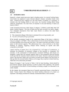
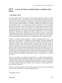
1 DESIGN OF TENSION MEMBERS 5 design of tension members INTRODUCTION TENSION MEMBERS are linear MEMBERS in which axial forces act so as to elongate (stretch) the member. A rope, for example, is a TENSION member. TENSION MEMBERS carry loads most efficiently, since the entire cross section is subjected to uniform stress. Unlike compression MEMBERS , they do not fail by buckling (see chapter on compression MEMBERS ). Ties of trusses [Fig 1(a)], suspenders of cable stayed and suspension bridges [ (b)], suspenders of buildings systems hung from a central core [ (c)] (such buildings are used in earthquake prone zones as a way of minimising inertia forces on the structure), and sag rods of roof purlins [Fig 1(d)] are other examples of TENSION MEMBERS .
2 Stay cables Stayed bridge Suspenders Suspension Bridge (b) Cable Supported Bridges (a) Roof Truss Tie Rafter Suspenders(c) Suspended Building (e) Braced Frame Fig. 1 TENSION MEMBERS in Structures X bracings Top chord (d) Roof Purlin SystemSag rod Purlin TENSION MEMBERS are also encountered as bracings used for the lateral load resistance. In X type bracings [ (e)] the member which is under TENSION , due to lateral load acting in one direction, undergoes compressive force, when the direction of the lateral load is changed and vice versa. Hence, such MEMBERS may have to be designed to resist tensile and compressive forces.
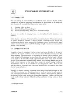
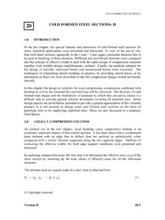
3 Copyright reserved Version II 5-1 DESIGN OF TENSION MEMBERS Version II 5-2 The TENSION MEMBERS can have a variety of cross sections. The single angle and double angle sections [Fig 2(a)] are used in light roof trusses as in industrial buildings. The TENSION MEMBERS in bridge trusses are made of channels or I sections, acting individually or built-up [Figs. 2(c) and 2(d)]. The circular rods [ (d)] are used in bracings designed to resist loads in TENSION only. They buckle at very low compression and are not considered effective. Steel wire ropes [ (e)] are used as suspenders in the cable suspended bridges and as main stays in the cable-stayed bridges.
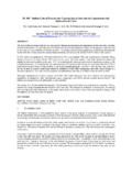
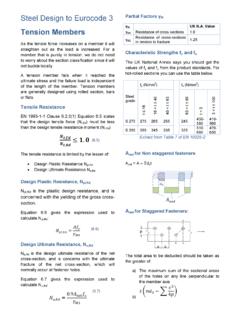
4 (a) (c) (d) (e) Fig. 2 Cross Sections of TENSION MEMBERS (b) BEHAVIOUR OF TENSION MEMBERS Since axially loaded TENSION MEMBERS are subjected to uniform tensile stress, their load deformation behaviour ( ) is similar to the corresponding basic material stress strain behaviour. Mild Steel MEMBERS (IS: 2062) exhibit an elastic range (a-b) ending at yielding (b). This is followed by yield plateau (b-c). In the Yield Plateau the load remains constant as the elongation increases to nearly ten times the yield strain. Under further stretching the material shows a smaller increase in TENSION with elongation (c-d), compared to the elastic range.
5 This range is referred to as the strain hardening range. After reaching the ultimate load (d), the loading decreases as the elongation increases (d-e) until rupture (e). High strength Steel TENSION MEMBERS do not exhibit a well-defined yield point and a yield plateau ( ). The offset load, T, as shown in Fig. 3 is usually taken as the yield point in such cases. T Fig. 3 Load Elongation of TENSION MEMBERS a b c dbs= DESIGN OF TENSION MEMBERS DESIGN strength of TENSION MEMBERS Although Steel TENSION MEMBERS can sustain loads up to the ultimate load without failure, the elongation of the MEMBERS at this load would be nearly 10-15% of the original length and the structure supported by the member would become unserviceable.
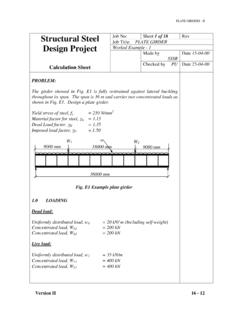
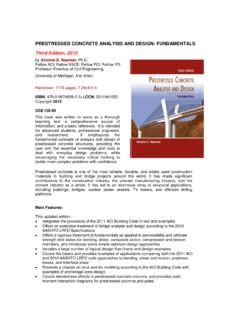
6 Hence, in the DESIGN of TENSION MEMBERS , the yield load is usually taken as the limiting load. The corresponding DESIGN strength in member under axial TENSION is given by (1)/0mgydgAfT = Where, fy is the yield strength of the material (in MPa), Ag is the gross area of cross section and m0 is the partial safety factor for failure in TENSION by yielding. The value of m0 according to IS: 800 is Plates under TENSION Frequently plates under TENSION have bolt holes. The tensile stress in a plate at the cross section of a hole is not uniformly distributed in the elastic range, but exhibits stress concentration adjacent to the hole [Fig 4 (a)].
7 The ratio of the maximum elastic stress adjacent to the hole to the average stress on the net cross section is referred to as the Stress Concentration Factor. This factor is in the range of 2 to 3, depending upon the ratio of the diameter of the hole to the width of the plate normal to the direction of stress. fyfy fu (d) Ultimate (b) Elasto-Plastic (c) Plastic (a) Elastic In statically loaded TENSION MEMBERS with a hole, the point adjacent to the hole reaches yield stress, fy, first. On further loading, the stress at that point remains constant at the yield stress and the section plastifies progressively away from the hole [ (b)], until the entire net section at the hole reaches the yield stress, fy, [Fig.]
8 4(c)]. Finally, the rupture ( TENSION failure) of the member occurs when the entire net cross section reaches the ultimate stress, fu, [Fig. 4(d)]. Since only a small length of the member adjacent to the smallest cross section at the holes would stretch a lot at the ultimate stress, and the overall member elongation need not be large, as long as the stresses in the gross section is below the yield stress. Hence, the DESIGN strength as governed by net cross-section at the hole, Tdn, is given by Fig. 4 Stress Distribution at a Hole in a Plate under TENSION )2(1 = where, fu is the ultimate stress of the material, An is the net area of the cross section after deductions for the hole [ (b)] and m1 is the partial safety factor against ultimate Version II 5-3 DESIGN OF TENSION MEMBERS TENSION failure by rupture ( m1 = ).
9 Similarly threaded rods subjected to TENSION could fail by rupture at the root of the threaded region and hence net area, An, is the root area of the threaded section ( ). (c) p g 1 2 3 4 (d) (b) Fig. 6 Plates with Bolt Holes under TENSION (a) Fig. 5 Stress in a threaded Rod (a) elastic droot dgross (b) elastic -Plastic (c) Plastic The DESIGN TENSION of the plates with hole or the threaded rod could also be governed by yielding of the gross cross section beyond the thread (with area equal to Ag) above which the member deformation becomes large and objectionable and the corresponding DESIGN load is given by )3(/0mgydgAfT = where, m0= The lower value of the DESIGN TENSION capacities, as given by Eqn.
10 2 and 3, governs the DESIGN strength of a plate with holes. Frequently, plates have more than one hole for the purpose of making connections. These holes are usually made in a staggered arrangement [ (a)]. Let us consider the two extreme arrangements of two bolt holes in a plate, as shown in (b) & 6(c). In the case of the arrangement shown in (b), the gross area is reduced by two bolt holes to obtain the net area. Whereas, in arrangement shown in , deduction of only one hole is necessary, while evaluating the net area of the cross section. Version II 5-4 DESIGN OF TENSION MEMBERS Version II 5-5n+ =Obviously the change in the net area from the case shown in (c) to (b) has to be gradual.