Transcription of 5. External Wall Construction
1 External wall construction265. External Wall ERECTION OF External PRECAST WALLSThe erection of precast walls generally involves the following steps:a)moving the precast wall panels from delivery truck or site storage yard to the designated locations forinstallation;b)raising the precast panels to the required elevation (and rotating to correct orientation if necessary);c)fixing the precast panels in position; andd)casting the wet joints and/or grouting and applying : Erection of a precast wall1. Remove precast wall fromdelivery the precast wall to requiredheight and orientation3. Position compressiblewaterproofing strip at joint4. Apply non-shrink precast wall into position6. Adjust position of precast wall7. Install plumb(and adjust if necessary)9.
2 Remove excess grout infill afterprecast wall is erectedFigure : Wet CASTING OF WET JOINTSThe use of wet joints is essential in minimising water seepage through the joint : Casting of wet joint connections1. Prepare continuity bars of wet joints2. Set up formwork for castingGood example of a wet jointBad example of a wet SEALING OF JOINTSP recast wall panels should be erected within theallowable Construction tolerances, with emphasisplaced on the gap size at the joints. This is importantto facilitate proper installation of backer rodand application of sealant to ensure effectivewatertightness at these surfaces at the joint should be sound,smooth, clean and free from all mortar dust or othercontaminants that may affect the adhesion ofsealant to the surfaces.
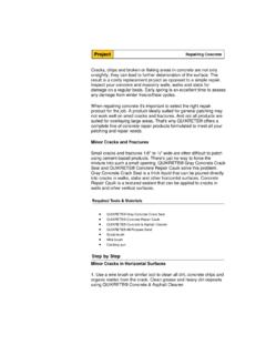
3 Some sealants may requirea primer to improve the adhesion. In such cases,manufacturer s advice should be sought to ensurecompatibility of the sealant and primer. As shownin Figure , poor surface preparation, resultingin loose particles and contaminants trapped inthe sealant can lead to premature failure of thesealant wall constructionexternal wall construction28 Figure : Premature failure of sealant due to contaminantsCoin to show thescale of photographSealantWhere form release agents, form oils, or other surfacecoatings had been used, it is recommended that thejoint surfaces be treated with a light sandblast,scarification or other approved methods in accordancewith the manufacturer s advice to improve the adhesionof the effective sealing, the sealant should be extrudedagainst a firm backing, such as a suitable backer rod,so that it is forced against the sides of the joint duringapplication.
4 The applied sealant should not adhere tothe backing material because the induced restraintand resultant stresses from three-sided adhesion couldlead to premature failure of the sealant system. A bondbreaker such as polyethylene film could also be used,in place of a backer rod to prevent three-sided applied sealant should be tooled to achieve aslightly concaved surface that is smooth, free of ridges,wrinkles, sags, air pockets and embedded : Tools for sealant application1. Sealant2. Sealant gun3. Backer rod (of various sizes)4. Masking tape5. Cutter6. Primer7. Brush for primer CAST IN-SITU REINFORCEDCONCRETE WALLSCast in-situ reinforced concrete (RC) walls are generallywatertight, unless cracks are formed in the walls or atthe joints between different elements.
5 Cracks may beformed as a result of poor concrete quality, poorworkmanship and/or unfavourable ensure watertightness at the joints between RC-RCmembers, the following preparatory work should becarried out before subsequent pour of concrete:a)roughen the joint surface while the concrete isstill green (eg. using a wire brush);b)remove laitance at the joint surface;c)rectify honeycombed areas with pressure groutingusing approved material; andd)apply a thin slurry coat of bonding agent at thejoint surface, where watertightness is is important to achieve the required alignment andverticality during casting so that there is minimalrectification work. The following should be observed:a)formwork should be in good condition;b)proper bracing and strutting; andc)thorough checks on plumb and alignment tie holes on External walls should be properlysealed to ensure watertightness of the buildingenvelope.
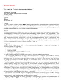
6 The following good practices should beadopted:a)wall plugs of resilient material (non-biodegradable) and of appropriate sizes shouldbe inserted into the form tie sleeve holes;b)surrounding concrete surfaces should be cleanedto remove all loose particles and dampened;c)a slurry coat of bonding agent , cement and water(refer to manufacturer s instructions on the mixratio) should be applied to the dampened surface;andd)non-shrink grout should be used to seal the slurry coat should still be fresh at time ofapplication of wall constructionFigure : Joint surface roughened to improve bonding at RC-RC jointexternal wall construction30 Figure : Form tie sleeve hole (sectional view)RC wallForm tie sleeveWall plugsNon-shrink groutFigure : Patching of form tie holes1.
7 Remove plastic cone2. Insert wall plug into sleeve3. Clean concrete surface4. Apply slurry of bonding agent , cement water5. Mix non-shrink grout6. Press grout mix into recess andfinish by removing excess groutfrom concrete workmanship in bricklaying is essential inensuring watertightness of should be proper co-ordination betweenexternal brickwork and other works. Setting out ofall works, including openings, sills and lintels,should be coordinated. A copy of the approvedbrickwall setting out drawings could be displayedat appropriate location for easy should be adequate scaffolding provided toenable workers to work from the outer side ofexternal walls to achieve a high standard of layingand pointing , MIXING AND USE OFMORTARFor enhanced performance, pre-packed mortar mix site batching of mortar mix, standard size containersshould be used to ensure correct proportion ofmaterials.
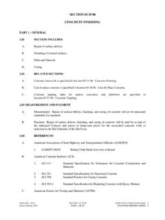
8 The use of shovels to gauge the amount ofmaterials cannot be relied upon to give consistentperformance. Additives should only be used upon theDesigner s permission, and with the advice from themanufacturer. Machine mixing is recommended toachieve a thorough blend of variations in the mixing time should be mixing may result in non-uniformity, poorworkability and low water retention of the mixing, on the other hand, may adverselyaffect the strength and bonding of mortar due to airentrainment. It is a good practice to regulate thequantity of mortar being mixed, so that the mortarcan be used up within the working OF BRICKSP roper setting out of the brickwork helps to reduceunnecessary cutting of brick units. Where cutting ofbrick units is needed, it is recommended thatappropriate cutting machine be used to produce clean-cut edges.
9 Alternatively, bricks could be cut using abolster and a hammer. However, this method tendsto produce less satisfactory wall constructionFigure : Measuring materials for mortar mixGauging by shovels cannot be reliedupon to give consistent mortar mix73 Example of using bucket batchingfor a 1:3 mixSandCement+3 Example of using gauge box batchingfor a 1:3 mixSandCement+Figure : Cutting of bricksMachine cutCutting with a bolster and hammerexternal wall OF BRICKSB rick units are generally porous and absorb moisturefrom the mortar during laying. This affects the adhesionbetween the brick units and the mortar. It is, hence,a good practice to dampen the brick units beforelaying, and to lay the mortar beds in shorter lengthsto reduce rapid loss of water from the mortar throughevaporation before the next course is being addition, the top surface of the brick walls wherethe previous laying stopped, and the surfaces ofabutting concrete slab/ beam/ column/ kerb shouldalso be well wetted before commencement of bricks, however, should not be overly wetted (donot soak the bricks in water), as this may result inexcessive efflorescence and staining of the units should be laid in full mortar bed with fullhead joints.
10 Frogged bricks should be laid with thefrog side facing up. The frogs should be completelyfilled with mortar to ensure no presence of voidsbetween the would be adversely affected if voidsare present in the cement mortar. Bricks should belaid in full and consistent mortar bed (Figure ).The practice of furrowing the bed joints and butteringonly the outer edges of the units should be cement mortar joints are usually less watertightthan the masonry units, average thickness of the mortarjoints should not be thicker than : Mortar jointsBrickwork without voidsBrickwork with voids37 Voids33external wall constructionThe joints should be raked out to a depth of about10mm while the mortar is still green to form anadequate key for plaster (Figure ).