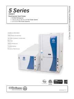
Transcription of 5 Series NSW Installation Manual - WaterFurnace
1 IM2506WN 06/16 Installation InformationWater Piping ConnectionsElectrical DataStartup ProceduresPreventive Maintenance5 Series NSW Installation ManualGeothermal Hydronic heat Pump500W115 Series NSW Installation MANUALT able of ContentsModel Nomenclature .. 4 General Installation Information .. 5 water Quality .. 6 Field Connected water Piping .. 7-9 Potable water Systems .. 10-11 Hydronic Section .. 12-13 Accessories and Options..14-15 Electrical data .. 16-17 Wiring Schematics ..18-21 External Control .. 22 Converting to a Dedicated Cooling Unit ..23 Unit Startup .. 24-25 The Aurora Base Control System ..26-30 The Aurora Advanced Control System .. 31-33 Reference Calculations ..34 Legend and Notes ..34 Pressure Drop .. 35 Operating Limits .. 35 Physical data ..36 Flow Rates ..36 Thermistor and Compressor Resistance ..36 Operating Parameters .. 37 Antifreeze Correction .. 38 Troubleshooting Guideline for Refrigerant Circuit .. 39HR data .
2 40-41HE data ..42-43 DHW HE data ..44 Heating and Cooling Cycle Analysis ..45 Troubleshooting Form ..46 Troubleshooting .. 47 Preventive Maintenance ..48 Service Parts ..49 Revision Guide.. 5145 Series NSW Installation MANUALM odel NomenclatureAll 5 Series NSW 500W11 product is safety listed under UL1995 thru ETL and performance listed with AHRI in accordance with standard 13256-1. The 5 Series 500W11 is also ENERGY STAR 4-6 7 8 9 10 11 Model N 5 Series Hydronic heat PumpCompressor Type S Single SpeedCabinet Configuration W water -to-WaterUnit Capacity 018, 025, 040, 050, 060, 075 Vintage* - Factory Use OnlyVoltage 1 208-230/60/1 Hot water Option1 0 No Hot water Generation 2 Hot water GenerationIntelliStart N None A IntelliStartControls OptionA Aurora Base Controls (ABC) B Aurora AdvanceG Controls (ABC AXB) C Aurora Performance3 D Aurora Performance3& RefrigerationFuture Option 0 StandardFuture Option S Standard Future Option S StandardWater Coil Option2 C Copper N - CuproNickel L Source CuproNickel & Load Copper S Source Copper & Load CuproNickelReversible Option H Heating Only R ReversibleRev.
3 : 18 January 2016S12 NOTES: 1 Available on 040, 050, 060, and 075 only. Hot water generator requires field installed external pump kit. 2 NSW018 and NSW025 heating only models are available only with copper double wall vented load coax for potable water , and are not designed to be converted to dedicated cooling units. 3 Flow meter for Performance option is shipped with unit, and must be externally field 14 151655 Series NSW Installation MANUALS afety ConsiderationsInstalling and servicing air conditioning and heating equipment can be hazardous due to system pressure and electrical components. Only trained and qualified service personnel should install, repair or service heating and air conditioning equipment. When working on heating and air conditioning equipment, observe precautions in the literature, tags and labels attached to the unit and other safety precautions that may all safety codes. Wear safety glasses and work gloves.
4 Use quenching cloth for brazing operations. Have fire extinguisher available for all brazing : Before installing, check voltage of unit(s) to ensure proper : Before performing service or maintenance operations on the system, turn off main power switches to the unit. Electrical shock could cause serious personal water ApplicationsFor process water applications, it is recommended that a secondary load heat exchanger be installed to prevent corrosion to the unit s primary coaxial coil. In situations where scaling could be heavy or where biological growth such as iron bacteria will be present, a closed loop system is recommended. Over a period of time, ground water unit heat exchanger coils may lose heat exchange capability due to a buildup of mineral deposits. These can be cleaned only by a qualified service mechanic as special pumping equipment and solutions are required. Never use flexible hoses with a smaller inside diameter than that of water and StorageMove units in the normal Up orientation as indicated by the labels on the unit packaging.
5 When the equipment is received, all items should be carefully checked against the bill of lading to ensure that all crates and cartons have been received in good condition. Examine units for shipping damage, removing unit packaging if necessary to properly inspect unit. Units in question should also be internally inspected. If any damage is observed, the carrier should make the proper notation on delivery receipt acknowledging the damage. Units are to be stored in a location that provides adequate protection from dirt, debris and Installation InformationWARNING: To avoid equipment damage, do not leave the system filled in a building without heat during cold weather, unless adequate freeze protection levels of antifreeze are used. heat exchangers do not fully drain and will freeze unless protected, causing permanent damage. Unit LocationProvide sufficient room to make water and electrical connections. If the unit is located in a confined space, provisions must be made for unit servicing.
6 Locate the unit in an indoor area that allows easy removal of the access panels and has enough space for service personnel to perform maintenance or repair. These units are not approved for outdoor Installation and, therefore, must be installed inside the structure being conditioned. Do not locate units in areas subject to freezing conditions. WARNING: Do not store or install units in corrosive environments or in locations subject to temperature or humidity extremes ( attics, garages, rooftops, etc.). Corrosive conditions and high temperature or humidity can significantly reduce performance, reliability, and service UnitsPrior to setting the unit in place, remove and discard the compressor hold down shipping bolt located at the front of the compressor mounting bracket. Units should be mounted level on a vibration absorbing pad slightly larger than the base to provide isolation between the unit and the floor. It is not necessary to anchor the unit to the floor.
7 Allow access to the front, back, and side access panels for servicing. Vibration Pad Mounting65 Series NSW Installation MANUALG eneralWater-to- water heat pumps may be successfully applied in a wide range of residential and light commercial applications. It is the responsibility of the system designer and installing contractor to ensure that acceptable water quality is present and that all applicable codes have been met in these installations. Failure to adhere to the guidelines in the water quality table could result in loss of heat pumps are not intended for direct coupling to swimming pools and spas. If used for this type of application, a secondary heat exchanger must be used. Failure to supply a secondary heat exchanger for this application will result in warranty exclusion for primary heat exchanger corrosion or TreatmentDo not use untreated or improperly treated water . Equipment damage may occur. The use of improperly treated or untreated water in this equipment may result in scaling, erosion, corrosion, algae or slime.
8 The services of a qualified water treatment specialist should be engaged to determine what treatment, if any, is required. The product warranty specifically excludes liability for corrosion, erosion or deterioration of Cupronickel316 Stainless SteelpHAcidity/Alkalinity7 - 97 - 97 - 9 ScalingCalcium andMagnesium Carbonate(Total Hardness)less than 350 ppm(Total Hardness)less than 350 ppm(Total Hardness)less than 350 ppmCorrosionHydrogen SulfideLess than ppm (rotten egg smell appears at ppm)10 - 50 ppmLess than 1 ppmSulfatesLess than 125 ppmLess than 125 ppmLess than 200 ppmChlorineLess than ppmLess than ppmLess than ppmChloridesLess than 20 ppmLess than 125 ppmLess than 300 ppmCarbon DioxideLess than 50 ppm10 - 50 ppm10 - 50 ppmAmmoniaLess than 2 ppmLess than 2 ppmLess than 20 ppmAmmonia ChlorideLess than ppmLess than ppmLess than ppmAmmonia NitrateLess than ppmLess than ppmLess than ppmAmmonia HydroxideLess than ppmLess than ppmLess than ppmAmmonia SulfateLess than ppmLess than ppmLess than ppmTotal Dissolved Solids (TDS)
9 Less than 1000 ppm1000 - 1500 ppm1000 - 1500 ppmLSI Index+ to + to + to Fouling(Biological Growth)Iron, FE2+ (Ferrous)Bacterial Iron Potential< ppm< ppm< ppmIron OxideLess than 1 ppm, above this level deposition will occurLess than 1 ppm, above this level deposition will occurLess than 1 ppm, above this level deposition will occurErosionSuspended SolidsLess than 10 ppm and filtered for max. of 600 micron sizeLess than 10 ppm and filtered for max. of 600 micron sizeLess than 10 ppm and filtered for max. of 600 micron sizeThreshold Velocity(Fresh water )< 6 ft/sec< 6 ft/sec< 6 ft/secNOTES: Grains = ppm divided by 17 mg/L is equivalent to ppm2/22/12 water QualityThe heat exchangers and water lines in the units are copper or cupronickel tube. There may be other materials in the building s piping system that the designer may need to take into consideration when deciding the parameters of the water an antifreeze or water treatment solution is to be used, the designer should confirm it does not have a detrimental effect on the materials in the WaterIn applications where the water quality cannot be held to prescribed limits, the use of a secondary or intermediate heat exchanger is recommended to separate the unit from the contaminated following table outlines the water quality guidelines for unit heat exchangers.
10 If these conditions are exceeded, a secondary heat exchanger is required. Failure to supply a secondary heat exchanger where needed will result in a warranty exclusion for primary heat exchanger corrosion or : Must have intermediate heat exchanger when used in pool and spa Quality Guidelines75 Series NSW Installation MANUALThe proper water flow must be delivered to each unit whenever the unit heats or cools. To assure proper flow, the use of pressure/temperature ports is recommended to determine the flow rate. These ports should be located adjacent to the supply and return connections on the unit. The proper flow rate cannot be accurately set without measuring the water pressure drop through the refrigerant-to- water heat exchanger (See Pressure Drop Table for water flow and pressure drop information). Normally about 3 GPM flow rate per ton of cooling capacity ( GPM per ton minimum) is needed. Both source as well as load fluid piping must be at least as large as the unit connections on the heat pump (larger on long runs).