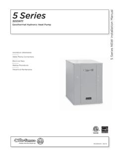
Transcription of 504W11 Geothermal Hydronic Heat Pump 3 to 5 …
1 IM2508WN 05/15 Installation InformationWater Piping ConnectionsElectrical DataStartup ProceduresPreventive Maintenance5 Series OptiHeat Installation Manual504W11 Geothermal Hydronic heat Pump3 to 5 Tons NEW Series5 Se5 SERIES OPTIHEAT 504W11 INSTALLATION MANUALT able of ContentsModel Nomenclature .. 4 General Installation Information .. 5 Field Connected water Piping .. 6-7 Hydronic Section .. 8-9 Accessories and Options.. 10-11 Electrical data .. 12-13 Wiring Schematics ..14-15 Unit Startup .. 16 Aurora Base Control.. 17-22 Reference Calculations .. 23 Legend and Notes .. 23 water Pressure Drop .. 23 Pressure Drop .. 24 Operating Limits .. 25 Physical data .. 25 Flow Rates .. 25 Thermistor and Compressor Resistance .. 26 Operating Parameters .. 26-27 Antifreeze Correction .. 28 Troubleshooting Guideline for Refrigerant Circuit .. 28 Heating and Cooling Cycle Analysis ..29 Troubleshooting Form ..30 Troubleshooting .. 31 Preventive Maintenance.
2 32 Service Parts .. 33 Revision Guide.. 3545 SERIES OPTIHEAT 504W11 INSTALLATION MANUALM odel NomenclatureAll 5 Series product safety listed under UL1995 thru ETL and performance listed with AHRI in accordance with standard 13256-1. The 5 Series is also ENERGY STAR *10RC34-67891011 Model N 5 Series Hydronic heat PumpCompressor Type E Vapor InjectionCabinet Configuration W water -to-WaterUnit Capacity 040, 050, 066 Vintage * - Factory Use OnlyVoltage 1 208-230/60/1 Hot water Option 0 No Hot water GenerationIntelliStart N None A IntelliStartControls Option B Aurora Advanced Controls Future Option 0 StandardFuture Option S Standard Future Option S StandardWater Coil Option C CopperReversible Option R Reversible H Heating OnlyRev.: 06 August 2014DS1221 SBSN13141516 VoltageNEW040050066208-230/60/1 - Voltage available in this size - Voltage and soft start available in this size55 SERIES OPTIHEAT 504W11 INSTALLATION MANUALG eneral Installation InformationSafety ConsiderationsInstalling and servicing air conditioning and heating equipment can be hazardous due to system pressure and electrical components.
3 Only trained and qualified service personnel should install, repair or service heating and air conditioning equipment. When working on heating and air conditioning equipment, observe precautions in the literature, tags and labels attached to the unit and other safety precautions that may all safety codes. Wear safety glasses and work gloves. Use quenching cloth for brazing operations. Have fire extinguisher available for all brazing : Before installing, check voltage of unit(s) to ensure proper : Before performing service or maintenance operations on the system, turn off main power switches to the unit. Electrical shock could cause serious personal : This heat pump is capable of producing hot water up to 150 F. All exposed piping surfaces shall be insulated to prevent serious personal injury that can occur from touching water piping. ApplicationUnits are not intended for heating domestic (potable) water or swimming pools by direct coupling.
4 If used for this type of application, a secondary heat exchanger must be and StorageMove units in the normal Up orientation as indicated by the labels on the unit packaging. When the equipment is received, all items should be carefully checked against the bill of lading to ensure that all crates and cartons have been received in good condition. Examine units for shipping damage, removing unit packaging if necessary to properly inspect unit. Units in question should also be internally inspected. If any damage is observed, the carrier should make the proper notation on delivery receipt acknowledging the damage. Units are to be stored in a location that provides adequate protection from dirt, debris and : To avoid equipment damage, do not leave the system filled in a building without heat during cold weather, unless adequate freeze protection levels of antifreeze are used. heat exchangers do not fully drain and will freeze unless protected, causing permanent damage.
5 Unit LocationProvide sufficient room to make water and electrical connections. If the unit is located in a confined space, provisions must be made for unit servicing. Locate the unit in an indoor area that allows easy removal of the access panels and has enough space for service personnel to perform maintenance or repair. These units are not approved for outdoor installation and, therefore, must be installed inside the structure being conditioned. Do not locate units in areas subject to freezing conditions. WARNING: Do not store or install units in corrosive environments or in locations subject to temperature or humidity extremes ( attics, garages, rooftops, etc.). Corrosive conditions and high temperature or humidity can significantly reduce performance, reliability, and service life. Mounting UnitsPrior to setting the unit in place, remove and discard both compressor hold down shipping bolts located at the front of each compressor mounting bracket.
6 Units should be mounted level on a vibration absorbing pad slightly larger than the base to provide isolation between the unit and the floor. It is not necessary to anchor the unit to the floor. Allow access to the front, back, top and side access panels for servicing. Vibration Pad Mounting65 SERIES OPTIHEAT 504W11 INSTALLATION MANUALThe proper flow rate cannot be accurately set without measuring the water pressure drop through the refrigerant-to- water heat exchanger (See Pressure Drop Table for water flow and pressure drop information). Normally about 3 GPM flow rate per ton of cooling capacity ( GPM per ton minimum) is needed. Both source as well as load fluid piping must be at least as large as the unit connections on the heat pump (larger on long runs).Never use flexible hoses of a smaller inside diameter than that of the water connection on the unit and limit hose length to 10 ft. per connection. Check carefully for water : water piping exposed to outside temperature may be subject to Loop Well water SystemsAlways maintain water pressure in the heat exchanger by placing water control valves at the outlet of the unit.
7 Use a closed bladder type expansion tank to minimize mineral deposits. Ensure proper water flow through the unit by checking pressure drop across the heat exchanger and comparing it to the figures in the pressure drop table. Normally, about 2 GPM flow rate per ton of cooling capacity is needed in open loop systems, ( GPM per ton minimum if entering source temperature is above 50 F [10 C].Some water control valves draw their power directly from the unit s 24V transformer and can overload and possibly burn out the transformer. Check total VA draw of the water valve(s) and ensure it is under 40 water from a heat pump can be disposed of in various ways depending on local building codes ( recharge well, storm sewer, drain field, adjacent stream or pond, etc.). Most local codes restrict the use of sanitary sewer for disposal. Consult your local building and zoning departments to ensure compliance in your unit is equipped with captive FPT water connections to eliminate egg-shaping from use of a backup wrench.)
8 For making the water connections to the unit, a Teflon tape thread sealant is recommended to minimize internal fouling of the piping. Do not over tighten connections. All supply and return water piping should be insulated to prevent excess condensation from forming on the water : Units are factory run-tested using propyleneglycol. Prior to connecting piping to unit, thoroughly flush heat exchangers. The piping installation should provide service personnel with the ability to measure water temperatures and pressures. The water lines should be routed so as not to interfere with access to the unit. The use of a short length of high pressure hose with a swivel type fitting may simplify the connections and prevent vibration. Optional stainless steel hose kits are available as an accessory final connection to the unit, the supply and return hose kits must be connected, and the system flushed to remove dirt, piping chips and other foreign material.
9 Normally, a combination balancing and close-off (ball) valve is installed at the return, and a rated gate or ball valve is installed at the supply. The return valve can be adjusted to obtain the proper water flow. The valves allow the unit to be removed for servicing. The proper water flow must be delivered to each unit whenever the unit heats or cools. To assure proper flow, the use of pressure/temperature ports is recommended to determine the flow rate. These ports should be located adjacent to the supply and return connections on the unit. Field Connected water PipingLine VoltageDisconnectLoad LiquidConnectionsWater OutWater InRubber BladderExpansion TankSolenoidValveFlow Regulator ValveShut-off Valve(to isolate solenoidvalve while acidflushing)Boiler Drains forHX FlushingShut-offValveVibration AbsorbingMesh or Air PadP/T PlugsNOTE: Valves and boiler drains must be installedso the heat exchanger can be acid Open Loop Installation75 SERIES OPTIHEAT 504W11 INSTALLATION MANUALF ield Connected water Piping Coupled Systems with Flow CenterOnce piping is completed between the unit, flow center and the earth loop, final purging and charging of the loop is needed.
10 A flush cart (at least a HP or kW pump) is needed to achieve adequate flow velocity in the loop to purge air and dirt particles from the loop itself. Antifreeze solution is used in most areas to prevent freezing. Maintain the pH in the range for final the system adequately to remove as much air as possible. Then, pressurize the loop to a static pressure of 50-75 psi [345-517 kPa]. This is normally adequate for good system operation. Ensure that the flow center provides adequate flow through the unit by checking pressure drop across the heat exchanger and by comparing it to the figures shown in the Pressure Drop tables. Usually, 3 GPM/ton [ L/s/kW] L/s/kW or minimum GPM/ton [ L/s/kW] of cooling capacity is needed in closed loop earth-coupled applicationsTypical Closed Loop Earth Coupled InstallationLine VoltageDisconnectLoad LiquidConnectionsVibration AbsorbingMesh or Air PadP/T PlugsUnit Connector Kitswith InsulationEarth Coupled LoopPiping with Insulation85 SERIES OPTIHEAT 504W11 INSTALLATION MANUALH ydronic SectionGeneral guidelines are shown below for component selection and design/installation criteria for the piping system.
