Transcription of 520-QS001B-EN-E PowerFlex 520-Series …
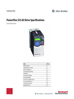
1 Quick Start PowerFlex 520-Series adjustable frequency AC drive Quick Start Quick Start Guide for PowerFlex 523 and PowerFlex 525 AC Drives PowerFlex 523 Catalog Number 25A, series B. PowerFlex 525 Catalog Number 25B. This Quick Start guide summarizes the basic steps needed to install, start-up and program the PowerFlex 520-Series adjustable frequency AC drive . The information provided DOES NOT replace the User Manual and is intended for qualified drive service personnel only. For detailed PowerFlex 520-Series information including EMC instructions, application considerations and related precautions, see the PowerFlex 520-Series User Manual, publication 520-UM001.
2 Topic Page General Precautions 2. Mounting Considerations 3. General Grounding Requirements 4. Fuses and Circuit Breakers 6. Technical Specifications 8. Power Wiring 9. I/O Wiring 10. Control Terminal Block 11. Prepare For drive Start-Up 16. Network Communication 34. Additional Resources These documents contain additional information concerning related products from rockwell automation . Title Publication PowerFlex 520-Series adjustable frequency AC drive User Manual 520-UM001. PowerFlex 4-Class Human Interface Module (HIM) DSI Quick Reference 22 HIM-QR001.
3 PowerFlex 525 Embedded EtherNet/IP Adapter User Manual 520 COM-UM001. PowerFlex 25-COMM-D DeviceNet Adapter User Manual 520 COM-UM002. PowerFlex 25-COMM-E2P EtherNet/IP Adapter User Manual 520 COM-UM003. PowerFlex 25-COMM-P PROFIBUS DP Adapter User Manual 520 COM-UM004. Dynamic Braking Resistor Calculator PFLEX-AT001. Wiring and Grounding Guidelines for PWM AC Drives DRIVES-IN001. Preventive Maintenance of Industrial Control and drive System Equipment DRIVES-TD001. Safety Guidelines for the Application, Installation and Maintenance of Solid State Control You can view or download publications at To order paper copies of technical documentation, contact your local Allen-Bradley distributor or rockwell automation sales representative.
4 PowerFlex 520-Series adjustable frequency AC drive ATTENTION: Before installing, configuring, operating or maintaining this product, read this document and the documents listed in the Additional Resources section for installing, configuring, or operating equipment. Users should familiarize themselves with installation and wiring instructions in addition to requirements of all applicable codes, laws, and standards. Installation, adjustments, putting into service, use, assembly, disassembly, and maintenance shall be carried out by suitably trained personnel in accordance with applicable code of practice.
5 If this equipment is used in a manner not specified by the manufacturer, the protection provided by the equipment may be impaired. Solid state equipment has operational characteristics differing from those of electromechanical equipment. Safety Guidelines for the Application, Installation and Maintenance of Solid State Controls, publication , available from your local rockwell automation sales office or online at describes some important differences between solid state equipment and hard-wired electromechanical devices.
6 General Precautions ATTENTION: The drive contains high voltage capacitors which take time to discharge after removal of mains supply. After power has been removed from the drive , wait three minutes to make sure DC bus capacitors are discharged. After three minutes, verify AC. voltage L1, L2, L3 (Line to Line and Line to Ground) to ensure mains power has been disconnected. Measure DC voltage across DC- and DC+ bus terminals to verify DC Bus has discharged to zero volts. Measure DC voltage from L1, L2, L3, T1, T2, T3 DC and DC+.
7 Terminals to ground and keep the meter on the terminals until the voltage discharges to zero volts. The discharge process may take several minutes to reach zero volts. Darkened display LEDs is not an indication that capacitors have discharged to safe voltage levels. ATTENTION: Only qualified personnel familiar with adjustable frequency AC drives and associated machinery should plan or implement the installation, start-up and subsequent maintenance of the system. Failure to comply may result in personal injury and/or equipment damage.
8 ATTENTION: This drive contains ESD (Electrostatic Discharge) sensitive parts and assemblies. Static control precautions are required when installing, testing, servicing or repairing this assembly. Component damage may result if ESD control procedures are not followed. If you are not familiar with static control procedures, reference A-B publication , Guarding Against Electrostatic Damage or any other applicable ESD protection handbook. ATTENTION: An incorrectly applied or installed drive can result in component damage or a reduction in product life.
9 Wiring or application errors, such as undersizing the motor, incorrect or inadequate AC supply, or excessive ambient temperatures may result in malfunction of the system. ATTENTION: The bus regulator function is extremely useful for preventing nuisance overvoltage faults resulting from aggressive decelerations, overhauling loads, and eccentric loads. However, it can also cause either of the following two conditions to occur. 1. Fast positive changes in input voltage or imbalanced input voltages can cause uncommanded positive speed changes.
10 2. Actual deceleration times can be longer than commanded deceleration times However, a Stall Fault is generated if the drive remains in this state for 1 minute. If this condition is unacceptable, the bus regulator must be disabled (see parameter A550 [Bus Reg Enable]). In addition, installing a properly sized dynamic brake resistor will provide equal or better performance in most cases. ATTENTION: Risk of injury or equipment damage exists. drive does not contain user-serviceable components. Do not disassemble drive chassis.