Transcription of 550 HC 20 PDF Temp - Steel Erection, Crane Services ...
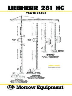
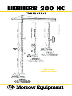
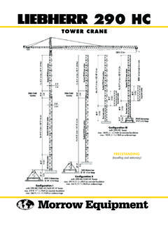
1 550 HC 20. TOWER Crane . 265 ft ( ). NOTE! See hook height charts inside. 11 x 19'-0" ( ) = 209'-0" ( ). 12 x 19'-0" ( ) = 228'-0" ( ). 12 x 19'-0" ( ) = 228'-0" ( ). Standard 550 HC tower sections Standard 550 HC tower sections 8'-0" Standard 550 HC tower sections 630 EC-H base section 40'-9". 500 HC-L base section 27'-11". 40'-9". 550HC Undercarriage 32'-10" ( ) Gauge 27'-11". Configuration III. 630 EC-H Undercarriage with 550 HC Tower 32'-10" ( ) Gauge max. 238 ft ( ) HUH on concrete foundation 27'-11". max. 264 ft ( ) HUH on undercarriage 500 HC-L Undercarriage Configuration II. 32'-10" ( ) Gauge with 550 HC/630 EC-H Tower max. 259 ft ( ) HUH on concrete foundation Configuration I max. 286 ft ( ) HUH on undercarriage with 550 HC/500 HC-L Tower max. 278 ft ( ) HUH on concrete foundation freestanding . max. 305 ft ( ) HUH on undercarriage Morrow Equipment Configurations 550 HC 20.
2 271'-4" ( ). Jib Tip Radius 31'-8". 11'-10". 13'-9". 86'-7" 6'-3". 265 ft ( ). Jib Tip Radius: 252'-3" ( ) 7,720 lbs 3 500 kg 246 ft ( ). Jib Tip Radius: 213'-11" ( ) 9,700 lbs 4 400 kg NOTE! See hook height charts below. 208 ft ( ). Jib Tip Radius: 174'-6" ( ) 15,210 lbs 12 x 19'-0" ( ) = 228'-0" ( ). 6 900 kg Standard 550 HC tower sections 70'-3" 170 ft ( ). Jib Tip Radius: 137'-2" ( ) 24,250 lbs 11 000 kg 131 ft ( ). Jib Tip Radius: 99'-5" ( ) 38,800 lbs 17 600 kg 53'-10" 93 ft ( ). freestanding . 44,090 lbs 20 000 kg NOTE! Consult Morrow for specific information regarding alternate tower configurations, alternate foundation details, dimensions, reac- tion forces and slab opening requirements. Hook Heights No. of Tower Hook Height Hook Height No. of Tower Hook Height Hook Height No. of Tower Hook Height Hook Height Tower Configuration Concrete Foundation 10m Undercarriage Tower Configuration Concrete Foundation 10m Undercarriage Tower Configuration Concrete Foundation 10m Undercarriage Sections I ft m ft m Sections II ft m ft m Sections III ft m ft m 0 500 HCL BTS 0 630 ECH BTS 1 550HC STS 1 550HC STS 1 550HC STS 2 550HC STS 2 550HC STS 2 550HC STS 3 550HC STS 3 550HC STS 3 550HC STS 4 550HC STS 4 550HC STS 4 550HC STS 5 550HC STS 5 550HC STS 5 550HC STS 6 550HC STS 6 550HC STS 6 550HC STS 7 550HC STS 7 550HC STS 7 550HC STS 8 550HC STS 8 550HC STS 8 550HC STS 9 550HC STS 9 550HC STS 9 550HC STS 10 550HC STS 10 550HC STS 10 550HC STS 11 550HC STS 11 550HC STS 11 1 550HC STS 12 1 550HC STS 12 1 550HC STS 1.
3 Lower top climbing unit to base of Crane prior to operating Crane at maximum hook height. Morrow Equipment Co., Configurations 550 HC 20. 86'-7" 271'-4". 10 x 19'-0" ( ) = 190'-0" ( ) max.*. 20'-0". 10'-6" ( ) 5'-6". Min. hook radius 19'-0". 9 x 19'-0" ( ) = 171-0" ( ). * NOTE! When top climbing, lower the Standard 550HC tower sections hydraulic climbing unit to the uppermost tie-in location prior to operating Crane at 8'-0" * Hydraulic Top maximum hook height. Restrictions apply, 195'-3". Climbing Unit please contact Morrow for additional information. **NOTE! When bottom climbing, the minimum distance between climbing 8 x 19'-0" ( ) = 152'-0" ( ) max. 4 x 19'-0" ( ) = 76'-0" ( ) min. frames is determined by number of tower sections installed above uppermost 48'-3" min.**. min. climbing frame and length of jib assembly installed.
4 Refer to Operations Manual for Hydraulic bottom additional information. 19'-0". climbing unit BOTTOM CLIMBING. with 550 HC Tower Sections Inside Structure [Site conditions Tie-In Centerline dependent] Assembly of Crane Anchor Face of Shoe NOTE! The tie-in assembly shown is an Structure 10 x 19'-0" ( ) = 190'-0" ( ) max. example of a typical installation. Please 4 x 19'-0" ( ) = 76'-0" ( ) min. note, however, that factors determining the installation of tie-in assemblies may when climbing. Direction of jib vary due to project specific conditions. [Site conditions dependent]. Contact Morrow for information regard- ing dimensions, reaction forces, tie-in locations and slab opening requirements.. Tie-in Tie-in Collar Struts NOTE! Please consult 550 HC 20 Connection plates by contractor Operations Manual before erecting, operating, climbing, servicing or dismantling 10'-0" ( ) min.
5 Crane . 20'-0" ( ) max. TOP CLIMBING. with 550 HC Tower Sections TIE-IN ASSEMBLY Tied to Structure Plan View Morrow Equipment Co., Radius and Capacities Tower Crane Model 550 HC 20. 2-Part Line Hook Maximum ft 66 79 93 105 110 120 131 140 150 160 170 180 190 208 223 246 265. Radius Capacity Radius m 265 ft 44,090 lbs 65 ft lbs 43,120 35,010 29,275 25,550 23,965 21,760 19,755 18,210 16,730 15,540 14,415 13,315 12,435 11,025 9,965 8,640 7,720. 20 000 kg kg 19 560 15 880 13 280 11 590 10 870 9 870 8 960 8 260 7 590 7 048 6 540 6 040 5 640 5 000 4 520 3 920 3 500. 246 ft 44,090 lbs 69 ft lbs 44,090 38,160 31,990 27,955 26,235 23,855 21,695 20,015 18,430 17,140 15,940 14,750 13,800 12,280 11,135 9,700. 20 000 kg kg 20 000 17 310 14 510 12 680 11 900 10 820 9 840 9 080 8 360 7 776 7 230 6 690 6 260 5 570 5 050 4 400. 208 ft 44,090 lbs 81 ft lbs 44,090 44,090 38,360 33,620 31,615 28,815 26,280 24,295 22,440 20,930 19,510 18,120 17,020 15,210.
6 20 000 kg kg 20 000 20 000 17 400 15 250 14 340 13 070 11 920 11 020 10 180 9 493 8 850 8 220 7 720 6 900. 170 ft 44,090 lbs 98 ft lbs 44,090 44,090 44,090 41,135 38,735 35,385 32,365 29,980 27,755 25,945 24,250. 20 000 kg kg 20 000 20 000 20 000 18 660 17 570 16 050 14 680 13 600 12 590 11 769 11 000. 131 ft 44,090 lbs 116 ft lbs 44,090 44,090 44,090 44,090 44,090 42,330 38,800. 20 000 kg kg 20 000 20 000 20 000 20 000 20 000 19 200 17 600. 93 ft 44,090 lbs 93 ft lbs 44,090 44,090 44,090. 20 000 kg kg 20 000 20 000 20 000. Capacity 44,090 lbs 45,000 lbs/20 410 kg 20 000 kg 38,800 lbs 2-Part Line 17 600 kg 40,000 lbs/18 145 kg 35,000 lbs/15 875 kg 30,000 lbs/13 610 kg 24,250 lbs 11 000 kg 25,000 lbs/11 340 kg 20,000 lbs/9 070 kg 15,210 lbs 6 900 kg 15,000 lbs/6 805 kg 9,700 lbs 4 400 kg 7,720 lbs 10,000 lbs/4 535 kg 3 500 kg 5,000 lbs/2 270 kg 0.
7 Jib Radius in feet 60 70 80 93 110 120 131 150 160 170 180 190 208 220 230 246 265. in meters Morrow Equipment Co., Foundations/Drive information Tower Crane Model 550 HC 20. Foundation Details 500 HC-L or 550 HC 630 EC-H base tower section tower section Reinforcing Reinforcing Steel each way Steel each way Foundation Elevation Foundation anchors (4) anchors (4). 7'-3" 7'-3". Reinforcing Reinforcing Steel each way Steel each way 7'-3". 7'-3". ". ". '-3. '-3. 1m Plan View 1m 10. 10. with 550 HC Tower Section with 500 HC-L or 630 EC-H Base Section on Concrete Slab on Concrete Slab Hoist Speed and Capacity Morrow offers the LIEBHERR 550 HC with a variety of alternative hoist units. For specific information regarding line speeds and lifting capacities, please contact a Morrow representative. Motor Information Drive Unit Horsepower Kilowatts Speed Trolley (2-part line) hp kW 25 - 50 - 164 - 328 fpm - 15 - 50 - 100 m/min Trolley FC (2-part line) * hp 11 kW 0 394 fpm 0 120 m/min Swing (fluid coupling) 2 x hp 2 x kW rpm Traveling (fluid coupling) 4 x 10 hp 4 x kW 0 82 fpm 0 m/min *Trolley drive with variable speed frequency converter available on 550 HC cranes with serial nos.
8 , and Contact Morrow for more information. Power Requirements 480 Volts 3-phase 60-cycle 225 Amperes service with 108 hp (80 kW) 4-speed hoist unit 300 Amperes service with 147 hp (110 kW) 4-speed hoist unit Specifications subject to change without notice. For other configurations and specifications, contact Morrow Equipment. Morrow Equipment Co., Component List 550 HC 20. Description Dimensions Weight Description Dimensions Weight LxWxH LxWxH. Tower Top H 30'-10" x 5'-9" x 6'-3" 11,685 lbs Jib Section H 39'-6" x 6'-4" x 6'-8" 8,575 lbs L W. x x 5 300 kg #611 L W. x x 3 890 kg Slewing Assembly H 22'-5" x 9'-9" x 9'-0" 37,765 lbs Jib Section H. 39'-5" x 5'-9" x 6'-6" 6,105 lbs (Complete) 1 L W. x x 17 130 kg #621 L W x x 2 770 kg Slewing Assembly H 15'-2" x 9'-9" x 9'-0" 21,230 lbs Jib Section H 39'-5" x 5'-9" x 6'-5" 4,885 lbs Upper Part 2 L W.
9 X x 9 630 kg #631 L W x x 2 215 kg Slewing Assembly H 7'-3" x 8'-0" x 8'-0" 16,535 lbs Jib Section H 39'-5" x 5'-9" x 6'-5" 4,355 lbs Lower Part 3 L W. x x 7 500 kg #632 L W x x 1 975 kg AC Hoist Unit w/Frame 4 H 8'-4" x 19'-3" x 6'-2" 23,280 lbs Jib Section H. 20'-8" x 5'-9" x 6'-5" 2,335 lbs 147 hp (110 kW) L W. x x 10 560 kg #635 L W x x 1 060 kg Counterjib Section #1 H 20'-10" x 6'-4" x 6'-1" 5,620 lbs Jib Section H. 39'-5" x 5'-9" x 6'-5" 5,070 lbs (Inner) L W x x 2 550 kg #633 L W x x 2 300 kg Counterjib Section #2 H 17'-1" x 6'-2" x 6'-1" 4,950 lbs Jib Section H. 39'-5" x 5'-9" x 6'-5" 3,440 lbs (Intermediate) L W x x 2 245 kg #634 L W x x 1 560 kg Counterjib Section #3 H 31'-8" x 7'-11" x 6'-1" 8,820 lbs Jib Section H 19'-2" x 5'-9" x 7'-7" 2,515 lbs (Outer) L W x x 4 000 kg #641 L W x x 1 140 kg Counterjib A 5 51'-10" x 7'-11" x 6'-1" 17,195 lbs Jib Assembly (Part 1) 9 77'-6" x 6'-4" x 6'-8" 20,945 lbs.
10 H. L W x x 7 800 kg for 170-ft to 265-ft jibs x x 9 500 kg Counterjib B 6 68'-3" x 7'-11" x 6'-1" 22,930 lbs Jib Assembly (Part 1) 9 77'-6" x 6'-4" x 6'-8" 21,605 lbs . H. L W x x 10 400 kg for 131-ft jib x x 9 800 kg Counterjib C 7 84'-8" x 7'-11" x 6'-1" 28,880 lbs Jib Assembly (Part 2) 10 190'-11" x 5'-9" x 7'-3" 29,320 lbs L W. H. x x 13 100 kg 265-ft ( ). x x 13 300 kg Standard Tower Section 22'-2" x 8'-0" x 8'-0" 14,155 lbs Jib Assembly (Part 2) 10 171'-7" x 5'-9" x 7'-3" 26,675 lbs . H. 550 HC (Pin/Pin) L W x x 6 420 kg 246-ft ( ) x x 12 100 kg Bottom Climbing Unit with H 20'-8" x 8'-4" x 8'-0" 40,940 lbs Jib Assembly (Part 2) 10 133'-2" x 5'-9" x 7'-3" 22,265 lbs hydraulics 500 HC-L (P/P) L W. x x 18 570 kg 208-ft ( ) x x 10 100 kg Base Section 8 40'-9" x 8'-10" x 8'-10" 40,125 lbs Jib Assembly (Part 2) 10 95'-2" x 5'-9" x 7'-3" 17,860 lbs.