Transcription of 550824K MH Series MH Analog Data Sheet0613 - …
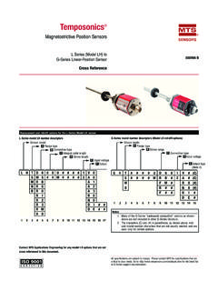
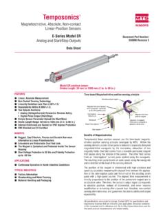
1 Temposonics Magnetostrictive, Absolute, Non-contact Linear-Position SensorsMH- Series Mobile Hydraulic in-Cylinder SensorModel MH Analog OutputData SheetSENSORS Document Part Number 550824 Revision KAll specifications are subject to change. Contact MTS for specifications and engineering drawings that are critical to your application. Drawings contained in this document are for reference only. Go to for the latest support documentation and related Linear, Absolute Measurement in Hydraulic Cylinders Non-Contact Sensing Technology Superior Accuracy, < Hysteresis < mm Repeatability, < Compact Design for Embedded Cylinder Applications Direct Analog Output: to Vdc, 4 to 20 mA Stroke length: 50 mm (2 in.) to 2500 mm (98 in.) Voltage input: 12/24 Vdc Shock Rating: 100 g (single hit) / IEC 68-2-27 Vibration Rating 25 g / 10-2000 Hz/IEC 68-2-6 200 V/m EMI ImmunityBENEFITS Rugged Mobile Sensor Direct Analog Output (Fully reversible)APPLICATIONS Continuous Operation In Harsh Mobile Conditions High Pressure Conditions For Welded and Tie-rod Cylinder ApplicationsTYPICAL INDUSTRIES Construction Agriculture Off-highway MachineryProduct overviewThe MH- Series Model MH sensor is designed with the mobile world in mind.
2 The Model MH sensor is validated in the field by customers worldwide. Performance is second-to-none with high EMI resistance of 200 V/m. Ruggedness is designed in ; 100 g shock and 25 g vibration rating. The model MH Analog sensor can be fully sealed and embedded in a cylinder to ensure a long operating life. Direct connec-tion to the Temposonics M12x1 connector system and other proven mobile connectors are Application ExampleMH- Series Model MH SensorMTS SensorsMH- Series Model MH, Temposonics Linear-Position Sensor - for Mobile Hydraulics Analog Output Product data Sheet, Document Part No.: 550824, Revision K 1/12, 5/12, 8/12, 12/12, 6/13 (US)2 Product specificationsParametersSpecificationsOU TPUTM easured variable:Linear Position measurementResolution:Range:Resolution:5 0 to 500 mm750 mm1,000 mm1,750 to to Vdc with failure output signalLoad resistance: > 10k mm mm mm mm mmCurrent:4 to 20 mALoad resistance: 250 at 12/24 Vdcpower supplyOutputs:Stroke length:50 mm to 2500 mm (2 in.)
3 To 98 in.)Measured in 5 mm ( in.) incrementsLinearity uncorrected:< full stroke (minimum mm in.)< full stroke (for short damping zone)Repeatability:< of full stroke Hysteresis: mm ( in.)Outputs:Direct Analog : Voltage: to Vdc , to Vdc to Vdc , to Vdc Current: 4 to 20 mA , 20 to 4 mAOperating voltage:12/24 Vdc (8-32 Vdc)Power consumption:1 W ELECTRONICSE lectrical isolation:500 Vdc (DC ground to machine ground)Polarity protection: Up to -36 VdcOvervoltage protection: Up to 36 VdcProduct Specifications and Output OptionsParametersSpecificationsENVIRONME NTALO perating conditions:Operating: -40 C (-40 F) to +105 C (221 F) Storage: -30 C (-22 F) to +105 C (221 F)90% relative humidity, no condensation EMI test:200 V/m: ISO 11452-5 ISO 14982 - Agriculture and forest machinery Shock rating:100 g (single hit)/IEC standard 68-2-27 (survivability)Vibration rating:25 g / 10 to 2000 Hz /IEC standard 68-2-6 WIRINGC onnection type.
4 One 4-wire with the M12x1 connector and flange (provides IP69K environmental protection when installed in a cylinder).ROD STYLE SENSOR (Model MH)material:Sensor rod: Stainless steel / AISI 304 LHousing: Stainless steel / AISI 303 Mechanical assembly: Flange housing 48 mm ( in.) dia., O-ring x mm NBR 80, backup ring x 48 x PTFES ealing:IP67 (IP69k when installed inside a cylinder with M12 x 1 in. connection type)Pressure rating:Sensor rod, 10 mm ( in.): Operating, 350 bar (5076 psi) Peak, 530 bar (7687 psi) Sensor rod, 7 mm ( in.): Operating, 300 bar (4350 psi) Peak, 400 bar (5800 psi) Magnet type:Ring magnet, Output range is factory programmable through entire stroke and is fully reversible. Output optionsThe MH- Series Model MH position Analog sensor provides direct Analog outputs: Voltage; to Vdc, to Vdc (reverse acting: to Vdc, to Vdc) Current; 4 to 20 mA (reverse acting: 20 to 4 mA) MTS SensorsMH- Series Model MH, Temposonics Linear-Position Sensor - for Mobile Hydraulics Analog Output Product data Sheet, Document Part No.
5 : 550824, Revision K 1/12, 5/12, 8/12, 12/12, 6/13 (US)3 MH- Series Model MH Analog Sensor Dimension and Magnet References Model MH sensor dimension referencesModel MH, rod-style Sensor Drawing is for reference only, contact applications engineering for tolerance specific 1. MH- Series Model MH rod-style sensor dimension reference Standard magnet selections (Model MH)SELECTION OF POSITION MAGNETS (MAGNET AND MAGNET SPACER MUST BE ORDERED SEPARATELY)A choice of three magnets are available with the Model MH rod-style sensor. Magnets must be ordered separately with Model MH position sensors. The standard ring magnet (part number 201542-2) is suitable for most RING MAGNETPart number 201542-2 MAGNET SPACERPart number 400633(used with magnet part no.: 201542-2)RING MAGNETPart number 400533 RING MAGNETPart number 401032 Material: Ferrite : mm ( in.)
6 : 33 mm ( in.)Thickness: 8 mm ( in.)Operating temperature: - 40 C (-40 F) to- 105 C to (221 F)Material: Non-ferrous, used with ring magnet (part no.: 201542-2) : 14 mm ( in.) : 32 mm ( in.)Thickness: mm ( in.)Material: Ferrite : mm ( in.) : mm (1 in.)Thickness: 8 mm ( in.)Operating temperature: - 40 C (-40 F) to- 105 C to (221 F)Material: Ferrite : mm ( in.) : 17 mm ( in.)Thickness: 8 mm ( in.)Operating temperature: - 40 C (-40 F) to- 105 C to (221 F)MTS SensorsMH- Series Model MH, Temposonics Linear-Position Sensor - for Mobile Hydraulics Analog Output Product data Sheet, Document Part No.: 550824, Revision K 1/12, 5/12, 8/12, 12/12, 6/13 (US)4 Model MH sensor installation referencesThe robust Temposonics Model MH sensor s new stainless-steel position sensor is designed for direct stroke measurement in mobile hydraulic cylinders.
7 The Temposonics Model MH sensor can be installed from the head side or the rod side of the cylinder depending on the cylinder Notes:1. Use a non-ferrous circlip to fix the The piston rod bore is dependent on hydraulic pressure and piston velocity. Minimum drilling for a (10 mm rod) should be mm. 3. There should be no less than 3 mm clearance between the end of the sensor rod and the bottom of the rod bore at full MH, rod-style sensor mechanical installation Drawing is for reference only, contact applications engineering for tolerance specific 2. MH- Series Model MH rod-style sensor mechanical installation exampleModel MH, rod-style sensor installation Drawings are for reference only, contact applications engineering for tolerance specific methods are possible in magnetic and non-magnetic applications (shown in Figures 3 and 4) and are entirely dependent on the cylinder design.
8 While the most common method of installation is from the rod side of the cylinder, installation from the head side of the cylinder is also possible. In both installation methods, the sensor seals the cylinder by using an O-Ring and backup ring which is installed on the sensor material installation referenceModel MH Rod-Style SensorInstallationFigure 3. Model MH installation in magnetic material using a non-ferrous magnet material installation referenceFigure 4. Model MH installation in non-magnetic material shown without magnet spacerSet screw detailMTS SensorsMH- Series Model MH, Temposonics Linear-Position Sensor - for Mobile Hydraulics Analog Output Product data Sheet, Document Part No.: 550824, Revision K 1/12, 5/12, 8/12, 12/12, 6/13 (US)5 Model MH Rod-Style SensorConnections, Wiring and Mounting Connections and wiringCONNECTION TYPEThe Temposonics M12 connector system (shown in Figures 7, 8, 9 and 10 ), meets the most stringent protection requirements important for the difficult environmental conditions of mobile hydraulics applications.
9 Protection type IP69K makes the robust metal housing not only completely dust and waterproof, even the harshest cleaning measures cannot damage the MH, rod-style sensor connector and pin assignments Drawings are for reference only, contact applications engineering for tolerance specific THE CONNECTOR SYSTEM TO THE CYLINDERF igure 7. The MH sensor is delivered by MTS together with the new connector system: The connector insert carrier is already connected to the sensor electronics, no soldering, any color or connection 8. The connector insert is taken out of the cylinder through a bore hole. The flange housing can be snapped into position easily from 5. Model MH sensor connection dimensions(1) Power Supply +12/24 Vdc(2) (3) 0 Vdc(4) Output: mA, VdcPin Assignment ( N06G) (1) Power Supply +12/24 Vdc(2) Output: mA, Vdc(3) 0 Vdc(4) 0 Vdc43214321 0 Vdc4321 Pin Assignment ( N06H) (1) (2) Power Supply +12/24 Vdc(3) 0 Vdc(4) Output: mA, VdcPin Assignment ( N06E) 0 VdcFigure 6.
10 M12 x 1 connector system pin assignmentsFigure 9. Four standard screws must be tightened to mount the connector system on the 10. With a corresponding mating molded plug the connector system fulfills a ingress rating of SensorsMH- Series Model MH, Temposonics Linear-Position Sensor - for Mobile Hydraulics Analog Output Product data Sheet, Document Part No.: 550824, Revision K 1/12, 5/12, 8/12, 12/12, 6/13 (US)6 MH- Series Model MH ordering informationUse the table below to configure your sensor part MH Rod-Style SensorOrdering InformationMHM312 3 45678 910111213141516 SENSOR MODEL=MH1-2MH= Rod-style with pressure fit flange housing 48 mm ( in.) STYLES=3C= Rod-style 10 mm ( in.) dia. damping zone mm ( in.)F= Rod-style 7 mm ( in.) dia. reduced damping zone mm ( in.)D= Rod-style 7 mm ( in.) dia.