Transcription of 5512301 H1 GB - Comptech Kft.
1 Technical description MULTICAL 601 Kamstrup A/S Industrivej 28, Stilling DK-8660 Skanderborg TEL: +45 89 93 10 00 FAX: +45 89 93 10 01 TECHNICAL DESCRIPTION MULTICAL 601 2 5512-301 H1 TECHNICAL DESCRIPTION MULTICAL 601 5512-301 H1 3 List of contents 1 General description .. 6 2 Technical Data ..7 Approved meter data ..7 Electrical Mechanical data ..9 Materials ..9 3 Type overview .. 11 Type and programming Type number combination ..12 PROG, A-B-CCC-CCC ..13 Display >EE< Configuration of MULTITARIFF ..22 >FF< Input A (VA), pulse divider >GG< Input B (VB), pulse divider ..23 Configuration of pulse outputs in the top >MN< Configuration of leak Data for configuration ..25 4 Dimentional sketches .. 26 5 Installation .. 27 Flow pipe and return pipe placing ..27 EMC conditions ..28 Climatic Electric installations ..28 6 Calculator 29 Energy calculation.
2 29 Application Flow measurement, V1 and V2 ..35 Power measurement, V1 ..36 Min. and max. flow and power, V1 ..37 Temperature measurement ..38 Display Info codes ..44 Tariff functions ..46 Data loggers ..50 Leak surveillance ..52 Reset TECHNICAL DESCRIPTION MULTICAL 601 4 5512-301 H1 7 Flow sensor connection .. 56 Volume inputs V1 and V2 .. 56 Flow sensor with active 24 V pulse output .. 58 Pulse inputs VA and VB .. 61 8 Temperature sensors .. 63 Sensor types .. 64 Cable influence and compensation .. 65 Pocket sensors .. 67 Pt500 short direct sensor set .. 68 9 Voltage supply .. 69 Integral D-cell lithium battery .. 69 Supply module 230 70 Supply module 24 70 Exchanging the supply unit .. 71 Mains supply cables .. 72 Danish regulations for connection of electric mains operated meters .. 72 10 Plug-in modules .. 73 Top modules .. 73 Base modules .. 79 Retrofitting modules.
3 84 11 Data 85 MULTICAL 601 data protocol .. 85 MULTICAL 66-CDE compatible 87 MC 601 communication paths .. 88 12 Calibration and verification .. 89 High-resolution energy reading .. 89 Pulse interface .. 89 True energy calculation .. 91 13 METERTOOL for MULTICAL 601 .. 92 Introduction .. 92 METERTOOL MULTICAL 601 .. 93 Verification with METERTOOL MULTICAL 601 .. 95 LogView MULTICAL 601 .. 98 14 Approvals .. 100 Type approvals .. 100 CE marking .. 100 Measuring instrument directive .. 100 TECHNICAL DESCRIPTION MULTICAL 601 5512-301 H1 5 15 Trouble-shooting .. 102 16 Disposal .. 103 17 Documents .. 104 TECHNICAL DESCRIPTION MULTICAL 601 6 5512-301 H1 1 General description MULTICAL 601 is a thermal energy meter with many applications. In addition to being a precise and reliable heat meter for battery or mains operation, MULTICAL 601 is also used for: Cooling measurement in water-based systems Bifunctional heat/cooling measurements in separate registers Leak surveillance of hot and cold-water installations Power and flow limiter with valve control Data logger Data communication Energy measurement in open systems In designing the MULTICAL 601 we have attached great importance to flexibility via programmable functions and plug-in modules (see chapter 10) in both the calculator top as well as in the base unit to ensure optimal use in a large number of applications.
4 In addition, the construction ensures that already installed MULTICAL 601 meters can be updated via the PC program METERTOOL. This technical description is prepared to give managers, meter electricians, consulting engineers and distributors the possibility of utilizing all functions available in the MULTICAL 601. Furthermore, the description is made for laboratories for the testing and verification process. During the preparation of this technical description we have drawn attention to the functional differences in changing from MULTICAL type 66-CDE into MULTICAL 601 to secure a safe product conversion for existing users. At each relevant paragraph that refers to this product conversion there will be comments marked as follows: 66-CDE MC 601 TECHNICAL DESCRIPTION MULTICAL 601 5512-301 H1 7 2 Technical Data Approved meter data Approval DK-0200-MI004-004, PTB , PTB , TS Standard EN 1434:2004 and OIML R75:2002 EU directives Measuring Instrument Directive, Low Voltage Directive, Electromagnetic Compatibity Directive Temperature range : 2 C Differential range.
5 3 K Accuracy EC ( + min/ ) % Temperature sensors -Type 67-A Pt100 EN 60 751, 2-wire connection -Type 67-B and 67-D Pt500 EN 60 751, 4-wire connection -Type 67-C Pt500 EN 60 751, 2-wire connection Compatible flow sensor types -ULTRAFLOW -Electronic meters with an active 24 V pulse output -Mechanical meters with an electronic pick-up unit -Mechanical meters with a Reed switch Flow sensor sizes [kWh] qp m3 m3/h [MWh] qp m3 m3/h [GJ] qp m3 m3/h EN 1434 designation Environmental class A and C MID designation Mechanical environment: Class M1 Electro-magnetic environment: Class E1 and E2 C, non condensing, closed location (indoor installation) TECHNICAL DESCRIPTION MULTICAL 601 8 5512-301 H1 Electrical data Calculator data Typical accuracy Calculator: EC ( + 2/ ) % Sensor set: ET ( + 4/ ) % Display LCD 7 (8) digits with a digit height of mm Resolution 9999999 Energy units MWh kWh GJ Gcal Data logger (EEPROM) Standard: 460 days, 36 months, 15 years, 50 info codes Option: Data loggers with lager depth and hour interval Clock/calendar Standard: Clock, calendar, compensation for leap years, target date Option: Real time clock with battery back-up Data communication Standard: KMP protocol with CRC16 used for optical communication and for top and base modules.
6 Option: MULTICAL 66-CDE compatible data for base modules Power in temperature sensors < 10 W RMS Supply voltage VDC 5% Battery VDC, D-cell lithium Stand-by current < 35 A excluding flow sensor Replacement interval - Mounted on the wall - Mounted on the flow sensor 10 years @ tBAT< 30 C 8 years @ tBAT< 40 C The replacement interval is reduced when using data modules, frequent data communication and high ambient temperature Mains supply 230 VAC +15/-30%, 50/60 Hz 24 VAC 50%, 50/60 Hz Insulation voltage 4 kV Power supply < 1W Back-up supply Integral super-cap eliminates operational disturbances due to short-term power cuts EMC data Meets EN 1434 class C (MID class E2) Temperature measurement T1 T2 T3 T4 Measuring range C C C N/A 67-A 2-W Pt100 Preset range C C C C Measuring range C C N/A N/A 67-B/D 4-W Pt500 Preset range C C N/A C Measuring range C C C N/A 67-C 2-W Pt500 Preset range C C C C Max.
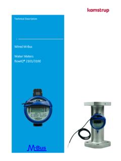
7 Cable lengths Pt100, 2-wire Pt500, 2-wire Pt500, 4-wire 2 x mm2: m 2 x mm2: 5 m 2 x mm2: 10 m 2 x mm2: 20 m 4 x mm2: 100 m - TECHNICAL DESCRIPTION MULTICAL 601 5512-301 H1 9 Flow measuring V1 and V2 ULTRAFLOW V1: 9-10-11 and V2: 9-69-11 Reed switches V1: 10-11 and V2: 69-11 24 V active pulses V1: 10B-11B and V2: 69B-79B EN 1434 pulse class IC IB (IA) Pulse input 680 k pull-up for V 680 k pull-up for V 12 mA at 24 V Pulse ON < V in > msec. < V in > 50 msec. < 4 V in > msec. Pulse OFF > V in > 10 msec. > V in > 50 msec. > 12 V in > 10 msec. Pulse frequency < 128 Hz < 1 Hz < 128 Hz Integration frequency < 1 Hz < 1 Hz < 1 Hz Electrical isolation No No 2 kV Max. cable length 10 m 25 m 100 m Pulse inputs VA and VB VA: 65-66 and VB: 67-68 Water meter connection FF(VA) and GG(VB) = Electricity meter connection FF(VA) and GG(VB) = Pulse input 680 k pull-up for V 680 k pull-up for V Pulse ON < V in > sec.
8 < V in > sec. Pulse OFF > V in > sec. > V in > sec. Pulse frequency < 1 Hz < 3 Hz Electrical isolation No No Max. cable length 25 m 25 m Requirements to external contact Leakage current at function open < 1 mA Pulse outputs CE and CV - via top module Type Open collector (OB) Pulse length Optional 32 msec. or 100 msec. for top module 67-04 (32 msec. for 67-06) External voltage VDC Voltage mA Residual voltage UCE 1 V at 10 mA Electrical isolation 2 kV Max. cable length 25 m Mechanical data Environmental class Meets EN 1434 class A and C Ambient temperature C non condensing, closed location (indoor installation) Protection class IP54 Storage temperature C (drained meter) Weight kg excluding sensors and flow sensor Connection cables mm Supply cable mm Materials Top cover PC Base unit PP with TPE packings (thermoplastic elastomer) Print box ABS Wall brackets PC + 30% glass TECHNICAL DESCRIPTION MULTICAL 601 10 5512-301 H1 Accuracy Figure 1 MULTICAL 601 typical accuracy compared with EN 1434.
9 TECHNICAL DESCRIPTION MULTICAL 601 5512-301 H1 11 3 Type overview MULTICAL 601 can be ordered in a countless number of combinations as required by the customer. First the required hardware is selected in the type overview. Then Prog , Config and Data are selected to suit the application in question. The meter is delivered completely configured and ready for use from the factory but it can also be retrofitted/reconfigured after installation. Please note that the items marked Totalprog can only be changed when the verification seal is broken. This requires that the change must be made at an accredited meter laboratory. New functions and modules for MULTICAL 601 are constantly being developed. Please contact Kamstrup A/S, if the described variants do not meet your requirements. Type and programming overview Type number 67-x-x-xx-xxx-xxx Total prog Select calculator, modules, sensor set and flow sensor Prog: A-B-CCC-CCC Total prog Config: DDD-EE-FF-GG-M-N Partial prog Data.
10 Partial prog TECHNICAL DESCRIPTION MULTICAL 601 12 5512-301 H1 Type number combination MULTICAL 601 Type 67- Sensor connection Pt100 2-wire (T1-T2) A Pt500 4-wire (T1-T2) B Pt500 2-wire (T1-T2-T3) C Pt500 4-wire (T1-T2) w/24 V pulse inputs D Top module No module 0 RTC (Real Time Clock) 1 RTC + Energy calculation + hourly data logger 2) 2 RTC + PQ or t-limiter + hourly data logger 3 RTC + data output + hourly data logger 5 RTC + 66-C compatibility + pulse outputs (CE and CV) 6 RTC + M-Bus 7 RTC + 2 pulse outputs for CE and CV + hourly data logger 8 RTC + Volume + hourly data logger 2) 9 RTC + 2 pulse outputs for CE and CV + hourly data logger + scheduler A RTC + 2 pulse outputs for CE and CV + prog.