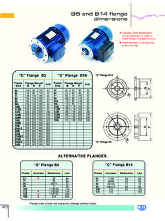
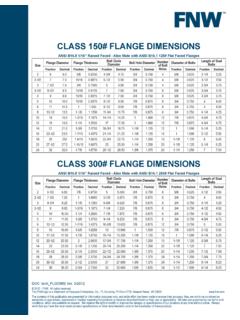
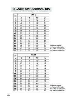
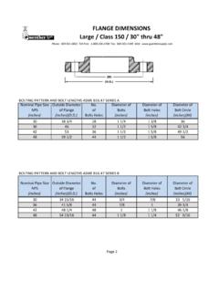
Transcription of 56C, 56J and Square Flange Mechanical Dimensions
1 56C, 56J and Square Flange Mechanical Dimensions 1 1 DIA. PADS &BOX FACESSQUARE WITHSHAFT L PITCH THD. 1/2 DEEP13/32 DIA. (4) HOLES, EQUALLYSPACED AS SHOWN45 6-1/210" BORECONCENTRICITYOFBORE WITH SHAFTWITHIN .003 1-7/8 11/16 1/85/32 Thd-Pitch: 7/16, 20 UNF, 2 ADia: 3995/4037 45 45 , Totally Enclosed Fan Cooled andExplosion Proof. All Dimensions are approxi -mate, not to be used for construction : Drawing shows rigid base. Foot mountingdimensions listed are identical for either rigid orresilient base mounting. For 56H CombinationFoot, refer to Diagram 1.
2 For C Flange motors,refer to Diagram 1 Suffix Y = Special Mount Z = Special Shaft 2 Diagram 3 Square FLANGE56H Combination Foot(56 & 143T/145T)Common to All Squirrel Cage MotorsFrameDEFBAUN-WKey Size422-5/81-3/427/322-1/163/81-1 Flat4832-1/81-3/82-1/21/21-5 Flat563-1/22-7/161-1/22-3/45/81-7/83/16 sq. x 1-3/856H3-1/2 Dia. 1 Dia. 12-3/45/81-7/83/16 sq. x 1-3/856 CSee Diagram 25/81-7/83/16 sq. x 1-3/856 JSee Diagram 25/82-7/16 Threaded143T3-1/22-3/422-1/47/82-1/43/16 sq. x 1-3/8145T3-1/22-3/42-1/22-1/47/82-1/43/1 6 sq. x 1-3 Mounting Holes 3/8-16, UNC 2B, Max.
3 Depth of Screw in Casting:5/8 .6250 3/16 Keyway2-1/16 56J 56J, 56C (FACE) .6250 CONVERSION

