Transcription of 6 Basic Pneumatic System Components - Gears EdS
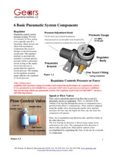
1 1 105 Webster St. Hanover Massachusetts 02339 Tel. 781 878 1512 Fax 781 878 6708 Copyright Gears Educational Systems 2005 6 Basic Pneumatic System Components Regulator Regulators control circuit pressure or force. Pressure is a measure of force acting over a specific area (P = force/area. These devices are fitted with mechanical Components that react to changes in the downstream air pressure. The regulator attempts to automatically maintain a constant (preset) pressure within a Pneumatic circuit as long as the supply (reservoir) pressure is greater than the required circuit pressure.)
2 The reading on the regulator-mounted gauge indicates the regulated or circuit pressure Note: Always use a regulator and a pressure gauge to monitor and control the performance of a Pneumatic System . Every Pneumatic System should have a pressure relief valve to prevent over pressure conditions that can develop within any Pneumatic System . The regulator used in the Gears -IDS kit has a self relieving feature. Speed or Flow Valves Flow valves control the speed of air flow into or out of a Pneumatic circuit or component. Flow is a measure of the volume of air moving through the circuit or component over a period of time (Flow = volume/time).
3 Flow control is adjusted using the needle valve. Screwing the needle valve outward increases the flow rate, the higher the flow rate, the faster the component will operate. Note: Air is regulated in one direction only, and flows freely in the other direction. The free flowing air direction is shown using a large arrow embossed on the valve. The regulated air flow direction is shown with a small arrow. Fine airflow control is best accomplished by regulating the flow of air out of a circuit or component. Figure Controls Pressure or Force 2 105 Webster St.
4 Hanover Massachusetts 02339 Tel. 781 878 1512 Fax 781 878 6708 Copyright Gears Educational Systems 2005 Note: Controlling air flow out of the cylinder is the preferred choice for accurate and smooth control of slower moving actuators. Single Acting Pneumatic cylinder or Linear actuator These devices are used to apply straight line (linear) pushing or pulling forces. Linear actuators are available in thousands of different configurations. These cylinders are fitted with pistons of various diameters and strokes of various lengths. They are most commonly specified as single acting (powered in one direction) or double acting (powered in both directions).
5 Single acting spring return cylinders are more economical with respect to air consumption. The Pneumatic cylinder supplied in the Gears -IDS Invention and Design System is a single acting, spring return cylinder . (see Figure and ) The Pneumatic cylinder used in the Gears -IDS kit has a bore (Interior diameter) of 16 millimeters or . Since 5/8 = , this cylinder can also be referred to as a 5/8 bore cylinder for computational purposes. When pressure is applied to the piston, the cylinder rod extends outward millimeters or . Important values to consider when designing or evaluating Pneumatic System performance are the surface area of the piston and the interior volume of the cylinder when the piston rod is fully extended.
6 The interior volume of the cylinder is determined by calculating the surface area of the piston and multiplying the area of the piston by the length of the stroke. Determine the Surface area of the piston and the interior volume of the cylinder using the following formula: cylinderLengthVolumeR =2 Sketching Exercise: Draw a sketch of the Gears -IDS cylinder . Include all the dimensions and calculations necessary to correctly determine the interior volume of the cylinder . Fig. Single Acting cylinder Flow Control Valve Return Spring Fig.
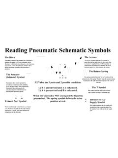
7 Fig. 3 105 Webster St. Hanover Massachusetts 02339 Tel. 781 878 1512 Fax 781 878 6708 Copyright Gears Educational Systems 20053-2 NC (Normally closed) Solenoid Valve Solenoid valves are electrically operated valves that control the direction and flow of pressurized air to and from Pneumatic actuators or circuits. Solenoid valves can be either mono-stable, (they spring return to a default condition either on or off) or Bi-stable, (having no preferred or default condition thus remaining where it was last positioned either on or off) Pneumatic valves can be operated by hand, (mechanical) electrically (solenoid) or air (piloted) operated.
8 The Gears -IDS kit includes a 3 port, 2 position electrically operated solenoid valve. The Gears -IDS 3-2 Pneumatic solenoid valve is described using 2 numbers. Example; The solenoid valve included in the Gears -IDS kit (pictured in fig ) is referred to as a 3-2 solenoid valve. This means the valve has 3 ports ( P1, A2 and E) and 2 possible conditions (Passing or not passing) and it is electrically operated (Solenoid). Ports and Positions of a 3-2 Valve The first number 3, refers to the number of ports or holes through which air moves into or out of the valve and the 2 refers to the number of valve positions or conditions.
9 Examine the valve closely. You will find 3 holes or ports in the base of the valve body. They are usually labeled as P1, A2 and E. The port labeled P1 is the pressure or inlet port. P1 connects to the pressure supply. The A2 port supplies pressurized air from P1 to an actuator or a circuit and in turn, allows air to pass from an actuator or a circuit to the E or exhaust port. The E port is open to the atmosphere. The 3-2 valve has only 2 possible valve positions or conditions; The valve can either be passing air from P1 to an actuator or circuit through A2 (the open condition) or, not passing air from P1 but rather passing Air from A2 to the E (exhaust) port (the closed condition).
10 Position One (Default) When the solenoid s electrical circuit is not energized (default condition), pressurized air cannot pass from the P1 port, through the valve to the actuator or circuit. The air pathway that exits in this (default) condition, connects the A2 port with the E (Exhaust) port and blocks the P1 port. In this condition air can only move from the actuator , through the A2 port to the E (Exhaust) port. The E port provides a means for air to exhaust to the atmosphere.(See figure ) Fig A2 E Fig. 4 105 Webster St. Hanover Massachusetts 02339 Tel.