Transcription of 6. SEEPAGE THROUGH DAMS - people.eng.unimelb.edu.au
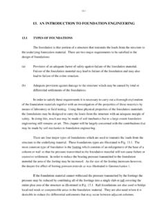
1 6-1. 6. SEEPAGE THROUGH DAMS. TYPES OF DAMS. The type of earth or earth and rockfill dam that is constructed at a particular location is usually dictated by the local availability of appropriate materials such as quarried rock, gravel, sand, silt or clay. A homogeneous dam (Fig. ) is one that is composed almost entirely of the one material which is usually relatively impervious. With this type of dam it is necessary to incorporate some type of downstream pervious drain with appropriately placed filters in order to control the SEEPAGE water. This is to prevent the occurrence of a piping failure by the internal erosion of the finer particles of the earthfill. If there exists a plentiful supply of rockfill, a thin core dam (Fig. ) could be constructed. The rockfill could be rolled by means of compaction equipment or dumped from trucks. Impervious cores having widths of 15% to 20% of the water head usually perform satisfactorily if adequately designed and constructed filter layers are incorporated.
2 When a wide range of construction materials is available within the vicinity of the damsite, a zoned earth and rockfill dam (Fig. ) incorporating all of these materials may be built. The term rockfill dam is usually restricted to a dam composed almost entirely of rockfill. The water barrier may consist of an upstream membrane of metal, concrete, asphalt or earthfill or there may be no water barrier at all. SEEPAGE THROUGH A HOMOGENEOUS EARTH DAM. It is considered to be poor design practice to permit the water, which will inevitably seep THROUGH the homogeneous earth fill, to discharge along the downstream face of the dam. This may be avoided by provision of a drain on the downstream side of the dam, such as the one shown in Fig. This pervious drain should extend sufficiently far in the upstream direction to ensure that the flow net is entirely contained within the homogeneous earth fill section. For a horizontal discharge face forming the boundary between the earth fill and the pervious drain, Kozeny (see Casagrande (1937)) has produced an exact solution for that portion of the flow net in the vicinity of the drain.
3 This solution is given by the flow lines and equipotential lines, which form a net of confocal parabolas in the lower portion of Fig. The focus of these parabolas is located at the upstream end of the pervious drain. In this case the line of SEEPAGE , which is the 6-2. Fig. Homogeneous Dam with a Chimney Drain Fig. Thin Core Dam Fig. Zoned Earth and Rockfill Dam 6-3. uppermost flow line is referred to as the Kozeny basic parabola. Since the line of SEEPAGE is a line of atmospheric pressure (that is, the pressure head is zero), changes in total head and elevation head along this line are identical. This means that there must be equal vertical intercepts between the points of intersection of the line of SEEPAGE with successive equipotential lines as illustrated in the sketch. If stand-pipes (piezometers) are placed at points along a particular equipotential line such as points A and B in Fig. , the water will rise in each of these stand-pipes until it reaches a level coincident with the point of intersection of the line of SEEPAGE with that particular equipotential line.
4 This characteristic provides a convenient technique for the determination of the pressure head or pore water pressure at any point within the flow net. The equation for the line of SEEPAGE is given by the following expression y2 - yo2. x = ( ). 2yo where y = yo at the point of intersection of the line of SEEPAGE with the y axis. In the upstream region of the flow net THROUGH the homogeneous earth fill the net of confocal parabolas will not be maintained but must alter in shape in order to satisfy the upstream boundary conditions. A convenient correction for the line of SEEPAGE at the upstream end has been proposed by Casagrande (1937). This correction is illustrated in Fig. (a). With this technique the basic parabola THROUGH point A is first located. At point B the flow line must intersect the upstream slope of the dam which is an equipotential line, at right angles. The upstream portion of the line of SEEPAGE is drawn from point B to join in gradually with the basic parabola at point C.
5 When the discharge face is not horizontal as illustrated in Fig. (b) the Kozeny basic parabola (with focus at point 0) no longer gives an accurate representation of the line of SEEPAGE in the vicinity of the discharge face. By means of a number of graphical solutions Casagrande has prepared a series of corrections to the basic parabola in terms of the slope of the discharge face as represented by the angle . These corrections are illustrated graphically in Figure (b). EXAMPLE. For the zoned earth dam illustrated in Fig. determine: (a) the rate of SEEPAGE discharge per unit width of dam THROUGH the earth fill, (b) the pore water pressure at point P, (c) The pore water pressure at point R. The permeability of the earth fill is m/sec. 6-4. Fig. Flow THROUGH a Homogeneous Dam 6-5. Fig. Approximate Corrections to Line of SEEPAGE (after Casagrande, 1937). 6-6. Equation ( ) (Geomechanics 1) applies to this situation so the problem reduces to the evaluation of the terms in that expression.
6 The loss of total head from the upstream to the downstream side of the dam is, as illustrated in Fig. , equal to 30m. The number of flow tubes Nf is 4 and the number of equipotential drops Nd is 10. Nf Q = k h per unit width Nd 4. = x 10-7 x 30 x 10. = x 10-6 m3/sec per m of dam = per m of dam It is clear from Fig. that the pressure head at point P is equal to the difference in elevation between point P and the point of intersection of the line of SEEPAGE and the equipotential line passing THROUGH point P. However, to illustrate fully the determination of pore pressure at point P, the problem will be solved here by a slightly longer method. First of all it will be assumed that the base of the dam is the datum (that is, an elevation head of zero). Since point P is located at a distance of above the datum the elevation head at point P is equal to the same value. The total head for the equipotential line passing THROUGH point P may be evaluated by considering the loss of total head between successive equipotential lines.
7 Since there is a total head loss THROUGH the dam of 30m and there are 10 equipotential drops, this means that of total head is lost between successive equipotential lines. Therefore the total head for the equipotential line passing THROUGH point P is equal to The pressure head at point P may then be found by subtracting the elevation head from the total head. Pressure head hpP = htP - heP. = - = pore pressure uP = w g h pP. = x x = 6-7. Fig. Fig. Flow THROUGH a Thin Core Dam 6-8. For the determination of the pore pressure at point R a similar procedure is followed to that described above. In this case, however, an equipotential line has not passed THROUGH point R. in the drawn flow net. It is therefore necessary to interpolate an equipotential line and this is shown by the dashed line in Fig. Now following the same procedure as previously described. Pressure head hpR = htR - heR. = - = pore pressure uR = w g h pR.
8 = x x = SEEPAGE THROUGH THIN CORE DAMS. A thin core dam is illustrated in Fig. in which the core or impervious soil zone is flanked on either side by a zone of rockfill. In many cases the permeability of the rockfill is in orders of magnitude greater than that of the relatively impervious core. In such cases the presence of the rockfill zones may be ignored for purposes of drawing a flow net. The upstream rockfill may be considered as an extension of the reservoir and the downstream rockfill may be considered as non-existent. The downstream slope of the core now becomes the discharge face for SEEPAGE passing THROUGH the core. It should be noted that the downstream slope of the core is neither a flow line nor an equipotential line. Because the distance in which the total head is dissipated is small in the case of a thin core dam compared with that for a homogeneous dam the total head gradient is greater and the velocity of flow of the water is greater.
9 With the greater velocity of flow there is a greatly increased risk of washing out the fine particles of soil from the core into the interstices of the rockfill on the downstream side of the dam. This action, if permitted to continue, could ultimately lead to a piping failure THROUGH the core of the dam. In order to reduce the probability of this occurring, it is necessary to place a transition zone or zones of material known as filters between the core and the rockfill on the downstream side of the dam. The design of these filters is discussed in section When a rapid drawdown occurs, that is, when a reservoir level is reduced relatively quickly, water which is inside the core of the dam near the upstream slope will tend to flow in an upstream direction. This means that it is also necessary to place filter zones between the rockfill on the upstream side of the dam and the core to remove the possibility of erosion of the fine particles of soil from the core of the dam.
10 6-9. FLOW THROUGH ANISOTROPIC MATERIAL. In all of the preceding discussion relating to SEEPAGE , it has been assumed that the flow region is isotropic, that is, the permeability is equal in all directions. In naturally occurring strata as well as in earth dams the horizontal and vertical permeabilities are often not equal. The Laplace equation as expressed by equation ( ) and for which the flow net is a graphical solution applies only to isotropic material. This means that in anisotropic materials (in which the horizontal and vertical permeabilities are unequal) flow nets of the type sketched in Fig. cannot be drawn. Fortunately a simple transformation may be made to the natural flow region in order to obtain an equivalent isotropic flow region within which the flow net may be sketched. This may be demonstrated by starting with the Laplace equation for anisotropic material 2h 2h kx x2+ky y2=0 ( ). If a new dimension X is defined by 1/2.