Transcription of 6424 Projected Beam Type Smoke Detector - cerber.pro
1 D400-18-001I56-494-11 RPRINTED IN MEXICO6424 Projected beam TypeSmoke DetectorINSTALLATION AND MAINTENANCE INSTRUCTIONSA Division of pittway 3825 Ohio Avenue, St. Charles, Illinois 601741-800-SENSOR2, FAX: 630-377-6495 SpecificationsGeneralRange:30 to 330 FeetSensitivity:30% 5% Total Obscuration, or55% 5% Total ObscurationResponse Time:Alarm:15 Seconds :15 Seconds Condition:95% or More ObscurationImproper Initial AlignmentSelf-compensation limit reached (service needed)Test/Reset Features:Obscuration Filters (ALARM/NO ALARM)Local Alarm Reset SwitchRemote Test and Reset Switch Capability(compatible with RTS451 Test Station with Magnet)Indicators:Alarm:Remote Output, Local LED (red)Trouble:Remote Output, Local LED (yellow)Normal Operation:Local LED (flashing green)Alignment Aid:LED Bar Graph (4 red LEDs)Relays:Alarm; TroubleEnvironmentalTemperature: 30 C to 55 C ( 22 F to 131 F)Humidity:10% to 93% RH NoncondensingMechanicalWeight: lbs (663 g)Transmitter: lbs (598 g)Mounting:Ceiling or Wall, Separate Mounting Brackets ProvidedWiring:Plug with Attached CableAdjustment Angle:Ceiling: 30 Horizontal/60 VerticalWall: 90 Horizontal/60 VerticalElectrical (Receiver)Voltage:20 to 32 VDCM aximum Ripple volts (Peak-to-peak)Current (24 VDC):Avg.
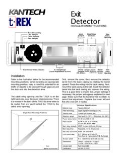
2 Standby:10mA Surge:19mA Contacts:.5A at 30 VAC/DCReset Time:.6 Seconds Time (after 5 min. reset): 1 Minute MaximumPower Loss:Retain Memory for 5 Minute MinimumElectrical (Transmitter) to 32 VDCM aximum Ripple volts (Peak-to-Peak)Avg. Current (24 VDC):10mA InstallingPlease thoroughly read this manual and applicable sectionsof System Sensor s Manual I56-506, Guide for Proper Use ofProjected beam detectors . Copies of this manual are avail-able from System DescriptionSystem Sensor Model 6424 is a long range Projected beamsmoke Detector designed to provide open area protection. Itis to be used with UL-listed, separately supplied power (4-wire) control panels only. The Detector consists of a sepa-rate transmitter and receiver. Smoke entering the areabetween the transmitter and receiver causes a reduction insignal at the receiver.
3 When the obscuration reaches one oftwo predetermined thresholds (chosen with a switch in thereceiver), the Detector generates an alarm signal. Completeblockage of the beam causes a trouble signal to avoid falsealarms. Slow changes in obscuration due to a build up ofdirt or dust on the lens of the Detector are compensated forby a microcontroller which continuously monitors the sig-nal strength and periodically updates the alarm and troublethresholds. When the self-compensation circuit reaches itslimit, the Detector generates a trouble signal, indicating theneed for LEDs at the receiver indicate the status of the detec-tor: a red LED for alarm, a yellow LED for trouble, and apulsed green LED for standby operation. The alarm signallatches and can be reset by a momentary power interrup-tion, by using the remote reset input to the receiver if usingthe remote test/reset station model RTS451, or with the lo-cal reset button located behind the rear door in the trouble signal automatically resets upon removing thecause of trouble.
4 In addition to these indicators, there arefour LEDs on both the receiver and the transmitter whichare used as a beam alignment aid. No additional equipmentis needed for alignment of the Detector contains one Form A (normally open) con-tact for alarm signals and one Form B (normally closed)contact for trouble signals. Supervision of power is accom-plished by installing a Power Supervisory End-of-Line RelayModule (model A77-716) at the end of the Detector powerloop. When power is applied to and through the detectors ,the EOL Power Supervisory Module is energized. The relaycontacts, along with the Detector s trouble relay contacts,can provide a closed series circuit in the control panel salarm-initiating loop. A loss in power or a trouble conditionat the Detector causes the respective EOL or trouble relay toopen, resulting in a trouble signal at the control ListDescriptionQuantityReceiver Unit1 Transmitter Unit1 Receiver Wiring Cable1 Transmitter Wiring Cable1 Wall Mounting Bracket2 Ceiling Mounting Bracket (inside part)2 Ceiling Mounting Bracket (outside part)2 Wall Bracket Screw2 Ceiling Bracket Screw2 Washers4 Allen Wrench1 Instruction Manual1 Test Filter1 Cable Exit Plug1 Hole Plug1 Detector PlacementThis section of the manual discusses the placement of pro-jected beam detectors .
5 Though this information is basedupon industry expertise, it is intended to be used only as atechnical guide. Always comply with the requirements ofapplicable codes and standards such as, NFPA 72, NationalFire Alarm Code, as well as directives of the Authority Hav-ing Jurisdiction (AHJ). For general information on theplacement of detectors , read System Sensor s Manual I56-506, Guide for Proper Use of Projected beam beam detectors are usually located with theirbeams parallel to the ceiling. However, they can bemounted vertically or at any angle to protect the area in-volved. Since beam detectors sense the Smoke buildup overa distance, they are ideal for locations with high can also be mounted on a wall or ceiling below thelevel of a spot type Detector , reducing the effects of airstratification.
6 Some typical locations would include largeareas with high ceilings such as atriums, warehouses, : Projected beam Smoke detectors should always bemounted to stable mounting surfaces. See theMOUNTING LOCATION section for fire codes specify spacing on a given center-to-centerdistance between detectors under ideal conditions. Thesespacings are based on rooms with smooth ceilings and nophysical obstructions between the contents being protectedand the detectors . Moreover, they are also based on a maxi-mum ceiling height, and on the assumption that the valueand the combustible nature of the contents of the room be-ing protected do not warrant greater protection or IN MEXICOIn a room with a smooth ceiling, detectors should bespaced between 30 and 60 feet. One-half that spacing be-tween the beam and the sidewall may be used as a Figure 1.
7 The beam Detector can be mounted with thereceiver on one wall and the transmitter on the oppositewall, or both suspended from the ceiling, or any wall/ceil-ing combination. In the case of the ceiling mount, the dis-tance from the end walls should not exceed one-quarter ofthe selected spacing ( ft. maximum if the spacing is 30ft.). See Figure 1. Spacing for smooth ceiling (side view):1/2 SS1 2. Spacing for smooth ceiling (top view):30 FEET MINIMUM330 FEET MAXIMUMTXRXSTXRX1/2 S MAXIMUM1/4 the case of peaked or sloped ceilings, codes may specifyspacing of detectors by using horizontal spacing from thepeak of the roof or ceiling. Figures 3 and 4 show the spac-ing for both the shed type and peaked type sloped 3. Sloped ceiling (shed type):S3 FT. S 4. Sloped ceiling (peaked type):1/2 SSS1/2 S3 DETECTORANYWHERE IN THIS AREATxRxA78-2035-01 Mounting LocationsBeam detectors require a stable mounting surface forproper operation.
8 A surface which moves, shifts, vibrates,or warps over time will cause false alarm or trouble condi-tions. Initial selection of a proper mounting surface willeliminate false alarms and nuisance trouble the Detector on a stable mounting surface, such asbrick, concrete, a sturdy load-bearing wall, support col-umn, structural beam , or other surface that is not expectedto experience vibration or movement over time. DO NOTMOUNT the beam Detector on corrugated metal walls,sheet metal walls, external building sheathing, external sid-ing, suspended ceilings, steel web trusses, rafters,nonstructural beam , joists, or other such IN MEXICOM ounting BracketsInstall a ceiling or wall bracket for both the receiver andtransmitter so that when mounted, the receiver and thetransmitter will be at approximately the same height.
9 Eachceiling bracket is composed of two parts that should be as-sembled with inside part between the ceiling and outsidepart as shown in Figure 5. The brackets should be mountedso that the slot in the front of each bracket is facing theother bracket. Mount the brackets only on solid structuresof the building. To avoid unwanted alarms due to wallmovement, do not mount to flexible walls, such as sheetmetal walls (see MOUNTING LOCATIONS). Mount brack-ets with a separation of at least 30 feet but not more than330 6. Ceiling mouting bracket assembly:CEILINGSCREWSSLOT IN FRONTOF BRACKETOUTSIDEPARTINSIDEPARTCEILINGA78-2 041-01 Concreteor BrickGood MountingSurfacePoor MountingSurfaceSheetMetalPoor MountingSurfaceGood MountingSurfaceFigure 5. Good and poor mounting surfaces:A78-2652-00 Wiring Installation GuidelinesAlways install all wiring in compliance with the NationalElectrical Code, and/or the applicable local codes, and anyspecial requirements of the local authority having jurisdic-tion.
10 Proper wire gauges and suitable means for strain reliefshould be used. The conductors used to connect beamsmoke detectors to control panels and accessory devicesshould be color-coded to reduce the likelihood of wiring er-rors. Improper connections can prevent a system from re-sponding properly in the event of a wire used for the beam Detector shall be nosmaller than 18 gauge ( square mm). For best systemperformance, all wiring should be twisted pair and in-stalled in separate grounded conduit. Do NOT mix fire sys-tem wiring in the same conduit as any other electricalwiring. Shielded cable may be used to provide additionalprotection against electrical installing the beam Smoke Detector in applicationswhere flexible conduit will be used the BMB beam Mount-ing Bracket kit must be installed with the cable before wir-ing the unit, as per the instructions supplied with the applications that require flexible conduit to be mountedto the beam Smoke Detector , the model BMB kit can be or-dered those applications where the model BMB kit is not used,the two connectors with attached cable (6 conductor forthe transmitter and 16 conductor for the receiver) can bewired before the Detector is wiring, first remove the pre-cut insulation from the con-ductor to be connected, then use a wire nut to connect thedetector wire to the field wire.