Transcription of 649A Compact Pressure Controller - MKS Instruments
1 649 AElECTRONiC Pressure Controller WiTh MASS-FlO METER The MKS Type 649 is a single instrument that provides both Pressure control and flow metering. The Type 649 replaces multiple component subassemblies, for example Pressure controllers with separate flow meters used in applications such as backside wafer cooling systems (BWCS). The Compact Type 649 design allows for significant reduction in BWCS size and 649 Series Pressure Controller contains a capacitance manometer, mass flow meter, normally-closed proportioning control valve, and closed-loop control electronics. The Type 649 controls absolute Pressure . The Pressure transducer is a Baratron Capacitance Manometer, with Full Scale Pressure ranges from 10 Torr to 1000 Torr. Baratron Capacitance Manometers well-known for their percent of Reading accuracy, stability, and resolution provide precise measurements at lower pressures and over wider dynamic ranges than strain gage transducers. The patented mass flow sensor provides exceptional zero stability and accuracy of flow measurement.
2 Full Scale ranges from 10 sccm to 5000 sccm nitrogen equivalent are 649 is powered by 15 VDC at only 300 mA. The Pressure output and input control signals are 0-10 VDC. Two trip points are included in the 649, with LED status indicators, for use as simple on/off process limits. The 649 s control loop tuning parameters are preset for typical installation conditions, but are field adjustable for different conditions and optimum performance. The Proportional and Integral Term adjustments are simple rotary switches, providing a wide dynamic control the Type 649, a Pressure transducer monitors the Pressure to be controlled at the downstream end of the Controller . Actual Pressure is compared in the electronics to the Pressure set point signal. An appropriate signal is then generated to adjust the proportioning control valve to bring actual Pressure into agreement with the desired set point. The internal control valve can be specified with one of four orifices allowing Pressure control in systems with Full Scale flows from 10 sccm to 5 slm.
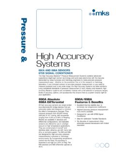
3 Features & BenefitsDesigned For The Most Demanding Processes Backside wafer cooling Fast response to set point with minimal overshoot Metal-sealed, cleanroom manufactured units meet critical high purity application needsReliable, Rugged, Repeatable Integral Baratron Capacitance Manometer provides accuracy, reliability, and wide rangeEasily Integrated Integral Pressure measurement and control with flow metering in a single package requires less space and reduces system cost Two alarm trip points for process limit control CE Mark compliant meets requirements for European Union Patented mass flow sensor* provides exceptional long-term accuracy and zero stability*US Patent 5461913. Foreign patent pending. Valve SolutionsFigure 1 Index Number Table (See Note)Figure 2 Orifice Selection Graph (See Note)Differential Pressure (psi)Differential Pressure (Torr)> 5 05 03 01 584210 . 51 0 0> 5 8 55 8 54 8 03 5 52 6 51 9 01 3 59 56 55 1 7 05 0 2 9 52 9 52 4 01 8 51 3 09 56 55 02 5 8 53 0 1 7 51 7 51 4 01 0 07 55 04 01 5 5 12 0 1 1 51 1 08 06 04 03 01 0 3 41 5 9 09 07 05 03 52 57 7 61 0 6 05 54 03 02 05 1 75 3 02 52 01 52 5 92 1 01 091 0 31 665 1.
4 7>2585 25851 5 5 17 7 64 1 42 0 71 0 35 1 . 72 5 . 9inlet Pressure (psia)inlet Pressure (Torr) Pressure RangeIn the Type 649 Controller , the Baratron Pressure Transducer measures absolute Pressure . Full Scale ranges of 10, 100, or 1000 Torr are available. Each 649 can control Pressure from Full Scale to less than 2% of Full Scale. Prudent design suggests choosing the lowest possible Full Scale for the application, taking into consideration the overpressure to which the sensor may be exposed (both normal and accidental).Valve OrificeThe flow through any orifice depends on the size of the orifice, the inlet and outlet pressures, and gas density. To simplify 649 orifice selection, use the following procedure: 1. On the Index Number Table in Figure 1, choose your inlet Pressure from the column of pressures on the left the Pressure that will be applied to the inlet of your 649. (Note that the values are absolute Pressure .) Next, from the row of pressures at the top of that table, select your differential (delta) Pressure this is the inlet Pressure minus your outlet Pressure .
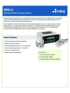
5 Locate the Index Number where your selected row and column intersect. 2. If you are using N2, skip to step #3. For other gases, calculate the Density Correction Factor by the following formula: Multiply this Density Correction Factor times the Index Number found in step 3, to determine your density-corrected Index Number. 3. Go to the Orifice Selection Graph (Figure 2) and locate your Index Number along the bottom axis. Draw a vertical line at your Index Number. This line will intersect with the Max. Flow Rate lines for available valve orifices. Choose the orifice whose maximum flow rate exceeds your requirements. Flow MeteringThe flow meter is simply Determine Full Scale flow rate and gas. If gas is N2, skip to # Divide the Full Scale flow rate by the thermal gas correction factor1 of the gas of choice relative to Choose the flow rate whose flow just exceeds/equals the equivalent N2 Contact MKS Applications Engineering for gas correction : The above procedure is provided as a reference guide to sizing the orifice for most typical applications.
6 To assure proper orifice size selection for the specific application conditions, particularly those where the procedure results in an orifice selection near the limit lines in the graph, please contact our Applications Engineers for assistance in selecting the proper valve orifice. Example 1 You want to control your process Pressure at 5 psia, with a flow rate of 1000 sccm of N2 . Your inlet Pressure is 15 psig, or 30 psia, giving a differential Pressure (delta P) of 25 psi. Approximating your delta P as 30 psi gives an Index Number value of 175. Drawing a vertical line on the Orifice Selection Chart at 175 indicates Orifice #3 would be the best choice. Example 2 You want to control a vacuum process at a Pressure of psia, with a flow rate of 2000 sccm of He. Your inlet Pressure is 15 psia, giving a differential Pressure (delta P) of 15 psi, resulting in an uncorrected Index Number value of 90. The gas density correction for He is calculated as N2 density/He density = = Multiplying by 90 gives a density-corrected Index Number of 234.
7 Drawing a vertical line on the Orifice Selection Chart at 234 indicates Orifice #2 would be the best Transducer Type Type 649 Pressure Ranges (Full Scales) 10, 20, 50, 100, 1000 mmHg (Torr)Flow Ranges (Full Scales) 10, 20, 50, 100, 200, 500, 1000, 2000, 5000 sccmTransducer Overpressure limit 45 psia or 2x , whichever is greaterOrifice Full Scale Ranges 50, 200, 1000, 5000 sccm (nominal flow rates for N2 with atm on inlet and vacuum on outlet)Maximum Differential Pressure 150 psi (consistent with transducer overpressure limit) Pressure Control Mode DownstreamPressure Reading Accuracy of Reading (includes linearity, hysteresis, and repeatability) Temp. Coefficients Zero: of C Span: of Reading/ C Time Response <100 msecPressure Control Range 2 to 100% of Accuracy of Time Response sec (excluding system time constant)Flow Reading Measurement Range 1% to 100% of Accuracy (including non-linearity, hysteresis, and non-repeatability referenced to 760 mmHg and 0 C) of Repeatability of Resolution of Temperature Coefficients Zero: < of C Span.
8 < of CPressure Coefficient < of Warm-up Time (w/in of steady state) <2 minMeter Response Time <100 msecOperating Temperature 0 to 50 C (32 to 122 F) Storage Temperature -20 to 80 C (-4 to 176 F)Power Required 15 VDC 5%, 300 mA Signals Pressure : 0 -10 VDC, standard (0-5 VDC optional) Flow: 0-5 VDCC onnector 15-pin male Type D Cable length 100 ft. (30 m) Sensitivity SAMA , 1-abc: < of Points Pressure Two open-collector transistors Rated 250 mA @ 30 VDC Adjustable 1 to 100% of Hysteresis 3% of Indicators Green LED s on when actuatedElectromagnetic Compatibility Fully CE Compliant to EMC Directive 2004/108/EC when used with an overall metal braided shielded cable, properly grounded at both endsMaterials Exposed to Gas Standard (metal sealed) 316L , 316L/VAR , Inconel , Nickel Optional (valve plug) Viton , Kalrez , Kel-F , or metalleak integrity External < 10-9 scc/sec He Internal (through closed valve)* Elastomer valve.
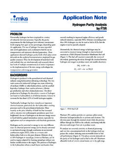
9 < 10-3 scc/sec He Kel-F/metal valve: < 2% of (N2 @ 25 psig to atm.)Fittings (compatible with) Male Swagelok 4 VCR , 8 VCRD imensions ( mm) x ( mm) (4 VCR) x (140 mm) lbs. ( kg)*Type 649 Control Valves should not be used for positive shutoff. Where positive shutoff is required, a separate valve should be installed. When selecting the location of an external shutoff valve, consideration should be given to the maximum Pressure rating of the internal transducer and to the possibility that leakage across the internal valve over time can build up and result in a sudden surge of gas. Note: The 649 Series controllers require flow to operate, but will not control Pressure in dead-ended (zero flow) InformationFigure 3 Cross section diagram.
10 Note: unless otherwise specified, dimensions are nominal values in inches (mm referenced).649A13T12C2 VROrdering Code Example: 649A13T12C2VR Code ConfigurationTypes 649 Electronic Pressure Controller with MFM 649A Pressure Range Full Scale 10 Torr (mmHg) 11T 20 Torr (mmHg) 21T 50 Torr (mmHg) 51T 100 Torr (mmHg) 12T 1000 Torr (mmHg) 13 TFlow Rate 10 sccm 11C 20 sccm 21C 50 sccm 51C 100 sccm 12C 200 sccm 22C 500 sccm 52C 1000 sccm 13C 2000 sccm 23C 5000 sccm 53 CValve Orifice (nominal flow range for N2 at 1 atm. DP) A (50 sccm) A #1 (200 sccm) 1 #2 (1000 sccm) 2 #3 (5000 sccm) 3 Valve Plug Material Viton V Kalrez D Metal* M Kel-F FFittings (compatible with) Swagelok 4 VCR male R Swagelok 8 VCR male TOptional Accessories Type 246 single-channel power supply/readout/set point control 246B Type 247C four-channel power supply/readout/set point control 247C Type 649 Y cable CB649-1-M1* Metal valve plug available on 200 sccm and larger valve orifice649A - 11/15 2003 MKS Instruments , Inc.