Transcription of 65-0126 - 7800 Series Rm7890A,B,C Relay Module - …
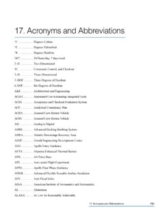
1 7800 Series Rm7890A,B,C . Relay Module The Honeywell RM7890 is a microprocessor based integrated burner control for automatically fired gas, oil or combination fuel single-burner appli- cations. The RM7890 consists of the Relay Module . Subbase and Amplifier are required to complete the system. Options include Keyboard Display Module , Personal Computer Interface, DATA. CONTROLBUS Module , Remote Display Mod- ule, First-Out Expanded Annunciator and COM- BUSTION SYSTEM MANAGER Software. The RM7890 is programmed to provide a level of safety, functional capability and features beyond the capacity of conventional controls. Functions provided by the RM7890 include auto- matic burner sequencing, flame supervision, system status indication, system or self-diagnostics and troubleshooting. Safety features: Sequence status. Closed loop logic test. Sequence time. Dynamic AMPLI-CHECK.
2 Total cycles of operation. Dynamic input check. Total hours of operation. Dynamic safety Relay test. fault history providing the six most recent faults: Dynamic self-check logic. Cycles of operation at the time of the fault . Expanded safe-start check. Expanded annunciator data at the time of the fault . Internal hardware status monitoring. fault message and code. Tamper resistant timing and logic. Hours of operation at the time of the fault . Access for external electrical voltage checks. Sequence status at the time of the fault . Application flexibility. Sequence time at the time of the fault . Communication interface capability. Diagnostic information: Dependable, long-term operation provided by microcom- Device type. puter technology. Flame amplifier type. First-out annunciation and system diagnostics are provided Flame failure response time. by a 2 row by 20 column Vacuum Fluorescent Display Manufacturing code.
3 (VFD) located on the optional Keyboard Display Module . On/Off status of all digital inputs and outputs. First-out expanded annunciation with 26 Light Emitting Software revision and version of RM7890 and op- Diodes (LEDs) for limits and interlocks (optional). tional Keyboard Display Module . Five (LEDs) for sequence information. Status of configuration jumpers. Interchangeable plug-in flame amplifiers. CONTENTS. Local or remote annunciation of RM7890 operation and fault information (optional). Specifications .. 2. Nonvolatile memory; RM7890 retains history files and Ordering Information .. 2. sequencing status after loss of power. Principle Technical Features .. 8. Remote reset (optional). Safety Provisions .. 8. Report generation (optional). Installation .. 9. Selectable relight or lockout on loss of flame. Wiring .. 11. Shutter drive output (RM7890B). Burner controller data (optional): Assembly.
4 13. Expanded annunciator status. Operation .. 15. Flame signal strength. Static Checkout .. 17. Hold status. Checkout .. 19. Lockout/alarm status. Troubleshooting .. 25. G. R. Rev. 2-94 Honeywell Inc. 1994 Form Number 65-0126 2. 1 65-0126 2. 65-0126 -2. Rm7890A,B,C . SPECIFICATIONS ORDERING INFORMATION. Specifications ELECTRICAL RATINGS, SEE TABLE 1: Fusing: Total Connected Load: 20A maximum, type Voltage and Frequency: 120 Vac (+10/-15%), 50 or 60 Hz FRN or equivalent. (+/- 10%). 2 ENVIRONMENTAL RATINGS: Power Dissipation: RM7890: 10W maximum. Ambient Temperature: Maximum Total Connected Load: 2000 VA. Operating: -40 F to 140 F. Storage: -60 F to 150 F. TABLE 1 TERMINAL RATINGS. Terminal No. Description Ratings G Flame Sensor Ground earth G earth Ground1. L2(N) Line Voltage Common 3 Line Voltage Supply (L1) 120 Vac (+10/-15%), 50 or 60 Hz (+/- 10%). 2,3.
5 4 Alarm 120 Vac, 1A pilot duty. 5 Unused 6 Burner Controller and Limits 120 Vac, 3A pilot duty or 1A pilot duty, ignition. 7 Unused 8 Pilot Valve/Ignition 120 Vac, Ignition and 50 VA pilot duty. 4. 9 Main Fuel Valve 120 Vac, 2A pilot 10 Ignition 120 Vac, F(11) Flame Sensor 60 to 220 Vac, current limited. 12 Unused 13 Unused 14 Unused 15 Unused 16 Unused 17 Unused 18 Unused 19 Unused 20 Unused 21 Unused 22 Shutter 120 Vac, (RM7890B). 1. The RM7890 must have an earth ground providing a connection between the subbase and the control panel or the equipment. The earth ground wire must be capable of conducting the current to blow the 20A fuse (or breaker) in event of an internal short circuit. The RM7890. needs a low impedance ground connection to the equipment frame which, in turn, needs a low impedance connection to earth ground. For a ground path to be low impedance at RF frequencies, the connection must be made with minimum length conductors having maximum surface areas.
6 Wide straps or brackets rather than leadwires are preferred. Be careful to verify that mechanically tightened joints along the ground path, such as pipe or conduit threads or surfaces held together with fasteners, are free of nonconductive coatings and are protected against mating surface corrosion. 2. Operating frequency chosen by RM7890 selection. 3. 2000 VA maximum connected load to RM7890 Assembly. 4. Can also be 120 Vac, 1A pilot duty. 5. Can also be 65 VA pilot duty with motorized valve, 1150 VA inrush, 460 VA open, 250 VA hold. Ordering Information When purchasing replacement and modernization products from your 7800 Series distributor, refer to the TRADELINE Catalog for complete ordering number. If you have additional questions, need further information, or would like to comment on our products or services, please write or phone: 1. Your local Home and Building Control Sales Office (check white pages of your phone directory).
7 2. Home and Building Control Customer Satisfaction Honeywell Inc., 1885 Douglas Drive North Minneapolis, Minnesota 55422-4386 (612) 951-1000. In Canada Honeywell Limited/Honeywell Limitee, 740 Ellesmere Road, Scarborough, Ontario M1P 2V9 International Sales and Service Offices in all principal cities of the world. Manufacturing in Australia, Canada, Finland, France, Germany, Japan, Mexico, Netherlands, Spain, Taiwan, United Kingdom, 65-0126 2 2. Rm7890A,B,C . SPECIFICATIONS. Humidity: 85% RH continuous, noncondensing. Vibration: environment. DIMENSIONS: Refer to Figs. 1 and 2. ! WARNING. Do not use non-shelf check ultraviolet flame WEIGHT: RM7890 with Dust Cover: 1 pound 13 ounces, detectors (C7027, C7035, C7044, or C7012A,C). unpacked. with the RM7890C. The RM7890C is designed for standing pilot IMPORTANT: Flame detection System available for use applications and does not conduct a Safe Start with RM7890.
8 To select your Plug-in Flame Signal Check. It cannot detect a failed non-self check Amplifier and applicable Flame Detector, see Table 2. flame detector. and Figs. 3-5. Inability to detect a failed flame detector could result in a fire or explosion hazard which can cause property damage, severe injury or death. TABLE 2 FLAME detection SYSTEMS . Plug-in Flame Signal Amplifiers Applicable Flame Detectors Flame Failure 1. Response Type Color Self-Checking Model Time Fuel Type Models Rectification Green No R7847A .8 or 3 sec Gas Rectifying Flame C7004, C7007, C7011. Rod Holdersd Complete Assemblies: C7008, C7009, Q179. No R7847A .8 or 3 sec Oil Rectifying C7003, C7010, C7013, Photocell C7014. No R7847A 3 sec Gas, oil, Ultraviolet C7012A, coal (PurplePeeper) 3. Dynamic c .8 or 3 sec Gas Rectifying Flame C7004, C7007, C7011. R7847B. AMPLI-CHECK Rod Holdersd Complete Assemblies: C7008, C7009, Q179.
9 Dynamic R7847Bc .8 or 3 sec Oil Rectifying C7003, C7010, C7013, AMPLI-CHECK Photocelle C7014. Dynamic R7847Bc 3 sec Gas, oil, Ultraviolet C7012A, AMPLI-CHECK coal (Purple Peeper). Dynamic R7847Cb 3 sec Gas, oil, Ultraviolet C7012E,F. Self-Check 2 coal (Purple Peeper). Infrared Red No R7848A 3 sec Gas, oil, Infrared C7015. coal (Lead Sulfide). Dynamic R7848Bc 3 sec Gas, oil Infrared C7015. AMPLI-CHECK coal (Lead Sulfide). Ultraviolet Purple No R7849A .8 or 3 sec Gas, oil Ultraviolet C7027, C7035, (Minipeeper) 3. Dynamic R7849Bc .8 or 3 sec Gas, oil Ultraviolet C7027, C7035, AMPLI-CHECK (Minipeeper) 3. Blue Dynamic b 3 sec Gas, oil, Ultraviolet C7076. R7886A. Self-Check 2 coal (Adjustable Sensitivity). 1 A sec Flame Failure Response Time Amplifier is required when the Relight option has been selected (JR2 is intact, see Table 3). The RM7890 will lockout and indicate a fault 46 if a second FFRT is used and jumper JR2 (Lockout) is not clipped and removed.
10 A The C7012A,C, C7027, C7035 and C7044 Flame Detectors should be used only on burners that cycle on-off at least once every twenty-four hours. Appliances with burners that remain on continuously for twenty-four hours or longer should use the C7012E,F Flame Detector with the R7847C. Amplifier or the C7076A,D Flame Detector with the R7886A Amplifier as the ultraviolet flame detection system. b Circuitry tests all electronic components in the flame detection system (amplifier and detector) 12 times a minute during burner operation and shuts down the burner if the detection system fails. c Circuitry tests the flame signal amplifier at least 12 times a minute during burner operation and shuts down the burner if the amplifier fails. d Order flame rod separately; see holder Instructions. e Use only Honeywell Photocell, part no. 38316. 2 Use with RM7890B only. 3 Do not used with RM7890C.