Transcription of 6m 4-Element Quad - KG4JJH - Amateur Radio …
1 6m 4-Element quad Antenna Build this portable short boom beam with over 8 dBd gain. Summer contests are a great reason to get away from it all and enjoy the pleasures of Amateur Radio . I like to combine the VHF and Field Day events with camping so my antennas need to be portable. I had planned on building a 6-element OWA Yagi1 for 6m SSB and CW, but, in an effort to reduce the antenna size and weight, I started looking at quads. The resulting quad has about the same gain as the Yagi while being smaller and lighter. The quad uses #12 bare wire, a 10 foot boom, and features electric fence post spreaders with synthetic lumber hubs. The hubs can be moved and locked down along the boom, allowing adjustments to be made after the antenna is assembled.
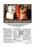
2 The wire elements are fastened to spreader clamps which then slip over the spreader ends. The antenna can be field assembled in about 10 minutes and requires only a wrench to secure it to the mast. Spreaders The element spreaders are fashioned from electric fence posts. These 3/8 OD x 48 long fiberglass posts are advertised to last 10 years outdoors and are relatively inexpensive at $ apiece. The only drawback is that the diameter is exactly 3/8 so they will not fit into holes drilled with a 3/8 bit. Therefore, the last inch on both ends is reduced to approximately OD by chucking the rod into a drill and holding a file against the rod. Alternatively, 3/8 OD fiberglass tubing2 can be used in lieu of the electric fence posts.
3 Although more expensive, they are manufactured with a reduced diameter that allows them to fit in 3/8 drilled holes. The spreaders are approximately 6% longer than the required distance so that they will flex once the elements are installed, pulling the elements taut. Cut four each of the spreader lengths in Table 1 and label them for faster assembly. A word of caution to builders is to avoid breathing fiberglass dust when sawing, drilling, or filing. If possible, cut outdoors and use a protective mask. Spreader Clamps Spreader clamps are made from OD fiberglass rod. The 3/8 x 1 deep spreader holes are drilled with a Forstner bit and a drill press. Drill the 1/8 element hole and then follow up on both sides with a countersinking bit to relieve the sharp edges and reduce stress on the elements wires.
4 The other end of the clamp is drilled and tapped for an 8-32 nylon thumbscrew. The 8-32 threads are in a blind hole, and tapping should be started with a taper tap until the tap touches the bottom of the hole, and then followed up with a bottoming tap. This is important as it allows the nylon thumbscrew to tighten the wire without dulling the thumbscrew threads. 6m 4-Element quad , KG4 JJH Page 1 of 5. When the wire element is threaded though the 1/8 hole and the thumbscrew is tightened to hold the wire the spreader clamps become part of the element assembly. Label the four spreader clamp/element assemblies to shorten assembly time. Boom The 10' boom is made from two 11/2 OD x 6' aluminum tubes joined together with a three foot length of 13/8 OD aluminum tubing and hardware.
5 If the tubing is slit on one end, install them with the slit ends on the outside and then trim to length after the antenna is assembled and tested. An 8 x 12 x 3/16 thick aluminum plate with stainless steel U- bolts forms the boom to mast bracket. Spreader Hub The four spreader hubs are cut from a piece of 2 x 4 synthetic lumber on a table saw. Drill the 11/2 and 3/8 holes with a Forstner bit and drill press. Enlarge the 11/2 boom holes using a dowel wrapped with sandpaper to allow the hubs to slide onto the boom. A. 1. /4-20 x 1 long setscrew secures each hub to the boom. elements Measure the #12 Flexweave elements and cut them to the lengths in Table 1. Avoid stretching the Flexweave wire when measuring or else the elements will be too long.
6 Mark the wire corners with a permanent marker and place marks 3/8 on either side of the corner marks. The next step is to thread the element wire through four spreader clamps. Center each clamp between the 3/4 wide marks made earlier and tighten the thumbscrew to lock the elements in place. Uninsulated butt splices were used for completing the Reflector, Director-1 and Director-2 loops and they seem to work well. Tin 1/4 of the element wire ends, insert them fully into the butt splices, secure with Sta-Kon type crimpers, and solder both sides. Table 1. 6m 4-Element quad Dimensions (All dimensions in inches). Ref DE Dir-1 Dir-2. Spreader Length Circumference Side Length 1st Corner Mark 2nd Corner Mark 3rd Corner Mark 4th Corner Mark Total Wire Length For the Driven Element, insert the wires through the center insulator and wrap and solder both sides.
7 The middle of the center insulator should be 301/4 from each corner mark. The feedpoint should be fabricated to minimize extra wire lengths to the antenna connector. Long coax pigtails will detune the Driven Element and lower resonance. For the prototype, a one foot length of RG8X coax with a female SO-239 connector on one 6m 4-Element quad , KG4 JJH Page 2 of 5. end and wire pigtails on the other end was fabricated. Remove 2 of outer insulator and install heat shrink tubing over the shield. Seal the open coax with silicone and heat shrink tubing over of the insulation cut. Solder the coax wires to the element on each side of the center insulator and use wire ties to secure the coax to the center insulator.
8 Dimensions and Modeling The dimensions for the quad are based on a design by G0 KSC3. I modeled his antenna in EZNEC and was delighted with the wide flat bandwidth, similar to an OWA Yagi. Using EZNEC 4, the free space model indicates a gain of dBi and 20 dB F/B ratio at MHz. In reference to a free space dipole ( dBi), the quad gain is dBd. For the region of interest (50 to MHz), the gain and SWR are relatively flat with a dB F/B peak at MHz. The modeled 50 SWR for 50, , and MHz is , , and , respectively (Figure 1). With the boom mounted at 25 feet elevation over average ground the modeled gain is dBi, dB F/B, with an 11 take-off angle. 25. 20. 15. 10. 5. 0. Gain (dBi) F/B (dB) SWR. Figure 1. Initial Assembly & Adjustment Slide the hubs onto the boom to their approximate positions and assemble the boom using four thread-cutting stainless steel screws.
9 Raise the boom to a convenient height and insert the Reflector spreaders into the Reflector hub. Next, slide the corner clamps with attached Reflector element over the spreader tips, flexing the spreaders toward the rear as 6m 4-Element quad , KG4 JJH Page 3 of 5. needed. Ensure that the spreaders are fully inserted into the hub and spreader clamps. Tension created from the flexed spreaders will keep the assembly secure. Repeat this process for the remaining three elements , taking care to place the Driven Element feedpoint at the bottom. Carefully measure the element to element spacing on the assembly and slide the hubs as necessary to meet the dimensions in Table 1. Assemble the boom to mast bracket between the Driven Element and Director-1 and adjust the position to balance the antenna.
10 For the prototype, the center of the boom was in line with the Director-1. element. Secure the hubs to the boom with the hub setscrews and mark the final hub and mounting bracket positions on the boom for future reference. Attach the coax to the feedpoint and secure it to the mast or boom for minimum pull on the driven element. For portability, the antenna breaks down into easily transportable pieces: 2 ea 11/2 OD x 5' boom with hubs and mounting bracket 1 ea 13/8 OD x 3' boom connector 16 ea 3/8 OD spreaders (various lengths less than 4 feet long). 4 ea Element/Spreader clamp assemblies Field Day On the day before Field Day 2010, the antenna was assembled and hung from a tree branch at my campsite with the boom at 21 feet.