Transcription of 7.3L Power Stroke Injector Replacement
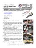
1 Power StrokeInjector ReplacementPage 1 of 4 Toll Free Sales & Customer Service: (866) 446 3360 IMPORTANT: Before starting installation, please be sure that all items which were supplied with the kit are accounted Tools: Pry Bar 12 Metric Sockets and Wrenches Lint Free Rags Allen Sockets (SAE)Recommended Parts: Injector O Ring Kit (8) AP0001 CCV O Ring Kit GZ 8 0041) Disconnect the negative cable from both ) Remove the air cleaner intake ducting from the air cleaner to the turbo. 3) Loosen the clamps from the Charge Air Cooler (CAC) boots at the intake spider on the drivers and passenger side. Slide boot off of the CAC pipe. (Fig 1)4) Loosen the clamps from the CAC boots on the intercooler flanges (both sides).
2 Slide the boots off of the CAC pipe. (Fig 2)5) Remove the MAP Sensor hose off of the spider and stow it by the MAP sensor on the passenger side. (Fig 1)6) Remove the CAC pipes from the engine ) Using a 10 mm socket, loosen the bolt on the 42 pin connector located on the drivers side valve cover. The bolt will be retained in the body side wire harness. Pull the wire harness away from the valve cover and tuck away on the fender well. (Fig 4)8) Remove heater hoses from the passenger side valve cover. Then remove the heater hose stand off clamps from the valve ) Disconnect the wiring harnesses from the valve cover gasket assy. (Fig 3)10) Remove the oil level dip stick from the passenger side of the ) Remove the bolts (10) from the valve covers and remove the valve covers.
3 Left side requires removal of CCV Doghouse (Breather assy)12) Disconnect the Under Valve Cover Harness (UVCH) from each Injector and from the glow plugs. Remove the Valve Cover Gasket assy. from the engine. (Fig 4)Fig 1 Fig 2 Fig 3 Fig 4 Page 2 of 4 Toll Free Sales & Customer Service: (866) 446 336013) Remove the bolt and oil deflector from the fuel Injector plate. (Fig 5)14) Remove the O/B retaining bolt on the fuel Injector . (Fig 6)15) You can now use a pry bar to get leverage under the hold down plate. Use the top side of the cylinder head to allow you to lift the Injector out of the bore. NOTE: Remove the aft Injector from each head first.
4 This will keep most of the fuel and oil that remains in the head limited to those two cylinders. You will evacuate them before you re install the ) Remove the remaining injectors in this same ) Ensure all of the copper tip washers and the o rings have been removed from the Injector bores before proceeding. Inspect the Injector bores and cups for any signs of damage. (Fig 7)18) Install the Injector O Rings onto the Replacement injectors as shown on the last page of these instructions. (Fig 10)19) Remove the glow plugs from all cylinders. (Fig 8)20) Place a small hose into the hole where the glow plug was removed. Make sure the hose goes down to the piston and then suck/vacuum out the oil/fuel mixture in the cylinder bore.
5 This will ensure you do not get a hydro lock on the cylinder once everything is removed. (Fig 9)21) Coat the new injectors with a liberal amount of clean motor oil. Make sure the o rings are coated well. 22) Making sure the copper Injector tip washer remains on the Injector , carefully place the Injector into the bore. Once installed, apply a even downward pressure on the Injector to seat it fully into the ) Repeat for all remaining ) Install the Injector retaining bolts in the outboard holes and torque to 10 ft ) Reinstall the oil deflectors and the bolts, torque to 9 ft ) Place the valve covers on the heads and turn the engine over by hand (2 3 full rotations) using the balancer bolt.
6 This will help clear the cylinders of any fluids. 27) Remove the valve covers and re install removed glow plugs tighten to 14 ft Power StrokeInjector ReplacementFig 9 Fig 8 Fig 7 Fig 5 Fig 6 Page 3 of 4 Toll Free Sales & Customer Service: (866) 446 336028) Install the valve cover gasket and reconnect the Fuel Injection Harness (UVCH) onto the glow plugs and the fuel ) Re Install the valve covers and (10) bolts. Tighten to 98 in lb. Re Install the CCV Doghouse (Breather Assy) using new GZ 8 004 O Rings. Torque bolts to 89 in ) Re install the oil level dip stick and ) Re install the heater hoses on the passenger side to the clamps and secure ) Re install the 42 pin connector and tighten the 10 mm bolt ) Re install the MAP Sensor hose onto the ) Install the CAC Tubes into the boots on the ) Install the CAC Tubes into the boots on the spider ) Locate the clamps on the CAC Boots and tighten to 60 in ) Re Install the air cleaner to turbo ) Re connect the negative ground cables onto the ) Fill the oil rail with clean motor oil.
7 You can use a large syringe to help fill the rail with the new oil. This can be done by removing the external #5 plugs on the ) Remove the plug from the top of the HPOP reservoir and ensure the oil level is topped off. If needed add clean motor oil to the reservoir and replace the ) Cycle the ignition key without cranking, turn key on for 30 seconds, shut off, turn back to on again for 30 seconds. Repeat this 3 4 times. This will ensure the fuel bowl and rails get fuel ) Crank the engine over for 30 seconds. Let it sit about 15 minutes then crank again. Do this for 4 5 cycles. The engine will not start as the valve cover connectors are not connected yet.
8 This will allow the oil pressure to build and to slowly bleed the air in the heads. You may find it necessary to loosen the oil rail plug to allow the air to escape. It is not always needed, but does help ) Reconnect the valve cover ) Crank the engine over until it starts. This may take several attempts to get the engine to start as there will be lots of air in the oil and fuel systems. Cranking for 30 45 seconds and then letting the starter rest for 90 120 seconds is a good practice. Disconnecting the ICP sensor may help it start quicker. The PCM will use a default ICP pressure when the sensor is disconnected. Make sure your batteries are fully charged during this ) Once the engine starts it will run rough until all the air is expelled from the heads.
9 This may take up to 50 miles of spirited driving to ) Verify the engine oil level is within limits on the dip stick after running the Power StrokeInjector ReplacementPage 4 of 4 Toll Free Sales & Customer Service: (866) 446 3360 Disclaimer of Warranties and LiabilitiesRiffraff Diesel disclaims any implied warranties of merchantability and fitness for a particular Diesel also disclaims any liability or consequential damages including, but not limited to,repair labor, rental vehicles, hotel cost, or any other inconvenience warranty is in lieu of all other warranties or guarantees, either expressed or implied, and shall notextend to any consumer or to any person other than the original thanks to Ken (Woodnthings on FTE) for the instructions and Power StrokeInjector ReplacementFig 8