Transcription of 7 Color Series 35 PSI, 60 PSI, 100 PSI Boost Gauge
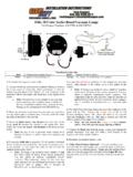
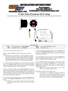
1 7 color series 35 psi , 60 psi , 100 psi boost gauge For Product Numbers: GS-C701_35 GS-T701_35 GS-W701_35. GS-C701_60 GS-T701_60 GS-W701_60. GS-C701_100 GS-T701_100 GS-W701_100. Wire Color Code: Yellow: 12v Constant (unswitched) Source (+) Black: Vehicle Ground ( - ). Red: 12v (switched) Source (+) Orange: 12v Dimmer (switched) Source (+) (optional). 1. Disconnect the negative battery cable. 5. Using automotive grade wiring (18 Gauge ), connect the yellow wire to a positive 12 volt constant (un-switched) source either on the Gauge Installation vehicle or in the fuse box. 2. Connect the Boost line to the Gauge using the female Note: If you are connecting the yellow wire directly to the compression fitting.
2 Once this is connected, run the Boost line battery, you MUST install a 3 amp fuse within 6-8 inches through the firewall and to your intake manifold. of the battery connection. Note: Make sure the Boost line is not pinched; the use of a rubber grommet through the firewall is required. 6. Using automotive grade wiring (18 Gauge ); connect the red wire to a positive 12 volt ignition (switched) source. It may be 3. Drill and tap your intake manifold to 1/8-27 NPT. Next, connect connected to the fuse panel, an accessory wire, or any positive 12. the included male compression fitting, which is attached to the volt source that turns on and off with the ignition. Boost line, to the tapped 1/8-27 NPT hole you just drilled in your intake manifold.
3 7. Using automotive grade wiring (18 Gauge ); connect the black Note: After drilling and tapping your intake manifold, be wire to any good (unpainted) ground connection. You may also sure to use vacuum and pen magnet to safely remove all route a wire directly to the negative side of the vehicle's battery. shavings from the manifold. You may also remove the top of your intake manifold before drilling for extra 8. The Night Time Dimming feature decreases the brightness of the protection against drill shavings. Gauge face by 30%. Connect the orange wire to the 12 volt Note: If you are installing this Gauge into a Dodge Ram, positive headlamp source. This allows the mode to be activated model years 98 to , you can install a Boost bolt when the headlights come on.
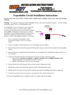
4 This step is optional and will not directly to your intake manifold. Installing this Boost bolt affect operation of the Gauge if it is omitted. does not require any drilling or tapping and can be Note: Do not connect the orange wire to a dimmer wheel. purchased at This will cause the Gauge lighting to flicker. Connecting the Power Wire Harness 9. Reconnect the vehicle's negative battery cable. 4. To make the wiring of your gauges easier you can purchase an If your Gauge (s) do not illuminate or do not recall your last expandable circuit. This component easily fits into your fuse panel saved Color , your switched and un-switched sources are and provides an additional fused power wire for accessories such reversed.
5 As gauges. The expandable circuit is available for purchase at If your Gauge (s) only illuminate red then the yellow wire for constant source is not connected properly. Be sure all of your wiring is correct to ensure proper Gauge operation. Additional Installation Information & Material Requirements GlowShift Gauges Approved Conductor Wires: Successfully installing GlowShift Gauges may require lengths of wire (sizes and quantity depend on vehicle, Gauge type, Gauge location and / or sensor location). For correct and proper GlowShift Gauge installation and operation, the use of 18 Gauge (wire diameter) automotive grade conductor wire with sheathing is recommended for one or more gauges per vehicle. When installing and routing wires from the engine compartment, to inside the vehicle cabin, always employ the use of a rubber grommet.
6 This will prevent and deter the stripping of power supply and / or sensor wires that is necessary to deliver vital statistics about your engine to your GlowShift engine monitoring instruments. Never use wire nuts to fasten or bound vehicle / Gauge or sensor wiring. Always use securing crimp connectors or solder individual wire junctions together for optimum Gauge installation and operation. GlowShift Gauges Approved Installation Accessories: GlowShift Gauges may require the installer or user to provide additional products, accessories or adapters for the correct installation and operation of a Gauge or sensor, as per the GlowShift Installation Instructions. When installing and routing hoses to or from the engine compartment, to inside the vehicle cabin, always employ the use of a rubber grommet.
7 This will prevent and deter the stretching or pinching of hoses that is necessary to deliver vital statistics about your engine to your GlowShift engine monitoring instruments. GlowShift Gauges Installation Instructions: Installation documents are solely to provide a guide for individuals that are mechanically and electronically able to install products. If you are unsure about the correct procedure of installation for a product or device, you should consult a professional mechanic or an Authorized GlowShift Installer. ONE YEAR NON-TRANSFERRABLE LIMITED WARRANTY AND DISCLAIMER. GlowShift Gauges, LLC ("GlowShift") warrants to the original retail consumer purchaser, and not any other purchaser or subsequent owner, that this Product will be free from defects in material or workmanship for a period of one (1) year from the purchase date.
8 For a period of one (1) year from the date of purchase, at no charge to the Purchaser, GlowShift will repair or replace this Product if it is determined by GlowShift to be defective. After the warranty period, the Purchaser must pay all charges for parts and labor. Coverage under this warranty is only valid within the United States, including its territories, as well as in certain other countries. Purchasers should check our website, , to determine the warranty coverage in the countries in which they are located. GlowShift does not warrant the installation of the Product, which is the sole responsibility of the Purchaser. Installation should be done by licensed professionals. Improper installation may cause damage to the Product and any vehicle in which it is installed, and may cause burns and electrical injury to individuals.
9 GlowShift's warranty does not cover any expenses incurred in removing Products that are defective or re-installing replacement Products in their place. During the warranty period, to have the Product repaired or replaced, the Purchaser must return the Product, freight prepaid by the Purchaser, to GlowShift (but for customers in the contiguous United States, GlowShift will pay the shipping charges if any Product fails during the first thirty (30) days after purchase). The Product must be returned in its original carton or in a similar package affording an equal degree of protection. GlowShift will return the repaired or replaced Product, freight prepaid, to the Purchaser. GlowShift does not provide Purchasers with temporary replacement units during the warranty period or at any other time.
10 This limited warranty is non-transferrable and will automatically terminate if the original retail consumer purchaser resells the Product or transfers the vehicle in which the Product is installed. An original retail consumer purchaser is a person who originally purchases the Product, or a gift recipient of a new Product that is in its original packaging and unopened. This limited warranty is subject to all of the following terms and conditions: TERMS AND CONDITIONS. 1. NOTIFICATION OF CLAIMS; WARRANTY SERVICE: If Purchaser believes that a Product is defective in material or workmanship, written notice with an explanation of the claim shall be given promptly by Purchaser to GlowShift. All warranty claims must be made within the warranty period, and any Products returned to GlowShift must be shipped in accordance with GlowShift's procedures (including use of RMA numbers supplied by GlowShift after notification).