Transcription of 8.0 Vegetated Swales - North Carolina Department of …
1 64 Vegetated Swales Overview of Practice Swales often serve to convey water around and away from businesses and residences. They are Vegetated , open channels, most often lined with grass. From a water quality perspective, they are preferable to pipes because they allow more soil and water contact, as well as more opportunity for infiltration. Filtration of sediment and debris can also occur within Swales , especially if the grass is kept relatively long. Figure shows grassed Swales in Durham and Wake Counties. Figure shows two Swales in the Raleigh-Durham area. Both have turf reinforcement mats. The former is mowed while the latter contains a taller grass stand. Determining Site Constraints CCAP does not allow a total riprap lined channel unless recommended by a PE. They cost share on TRM if it s within the designer s JAA or recommended by a PE. The first step in designing a Vegetated swale is to determine the constraints of the site. Slope The swale must convey flow from an upland area to an area that is lower in elevation.
2 Often, Swales will lead from a point in the watershed to an SCM or from an SCM to the existing drainage infrastructure. This information can be used to determine the allowable slope of the swale . The swale should have a relatively constant slope between its inception and destination. If changes in slope are necessary, they should be gradual. Slope (S) = elevation change from start to end (ft) length of swale (ft) Top Width 65 The maximum width of the swale may be dictated by site constraints. Determine the maximum width before beginning calculations. Side Slopes It may be desirable at some sites to leave the side slopes of a swale mild enough that they can be mowed with a riding lawn mower. If this is the case, a slope of 4:1 (H:V) or flatter is recommended, no steeper than 3:1 is recommended in most cases, and never more than 2:1. Triangular Swales may be used on small catchments less than 2 acres but is dependent upon the slope, the velocities may not allow it. Shape Both trapezoidal and triangular cross-sections are used for water quality Swales .
3 The depth of flow within these channels is shallow during small storms which allows increased soil and grass contact with the stormwater, and therefore increased infiltration and filtration. Triangular shaped Swales are more appropriate for small drainage areas, but trapezoidal Swales may also be used. Peak Flow Swales should be designed to convey the peak flow of the 10-year storm without overtopping, which is calculated using the Rational Method (section ). During extreme events ( 25 or 100-year storms), portions of the swale may be breached and should be repaired by the property owner as necessary. Depth and Velocity Calculations Swales should be able to carry their design flow without overtopping or eroding. If the velocity is too high for grass cover in a given swale design and the slope and cross-section cannot be adjusted, the swale can be reinforced with rip-rap or turf reinforcement matting, which can withstand a higher velocity. There are several approaches to designing a swale .
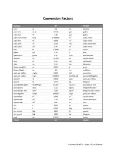
4 A site may have constraints which dictate the channel slope and cross-section, in which case the designer must simply ensure that the channel lining will be strong enough to handle the velocities produced. Conversely, there may be flexibility with respect to the channel cross-section, and the designer may choose to size it such that a simple grass lining, which reduces installation costs, will be sufficient to prevent erosion. Figure shows a diagram of a swale with a trapezoidal cross-section and illustrates some of the parameters discussed in this section. The equations used in trapezoidal channel design are as follows: Equation 8-1: The Continuity Equation Q = VA Where: Q = flow rate (cfs) V = average velocity of the cross-section (ft/s) A = cross-sectional area of the flow (ft2) 66 And: A = bd + xd2 (refer to figure ) Equation 8-2: Manning s Equation V = * (1/n) * R2/3 * S1/2 Where: V = velocity (ft/s) n = Manning roughness for a chosen channel lining (Table ) R = hydraulic radius (ft) S = channel bed slope (ft/ft) The hydraulic radius (R) is equal to the cross-sectional area of flow (A) divided by the wetted perimeter (Wp) (see Figure ), or for trapezoidal channels: R = (bd + xd2) / (b + 2dx) *all dimensions in ft For convenience, the top width of the trapezoidal channel can be calculated as: swale Top Width = b + 2Dx *all dimensions in ft Figure Trapezoidal swale cross-section.
5 The correct cross-section must be determined by trial and error. A computer spreadsheet or other software ( , TR-55) would be helpful in this process and may be obtained from SWCD personnel in Raleigh. First, assume a channel geometry, and use the Continuity Equation (Equation 8-1) and Manning s Equation (Equation 8-2) to determine the average velocity of flow for the design storm. By using the maximum permissible velocity method, it can be determined whether the channel will erode. Table shows maximum permissible velocities for a variety of channel linings. Manufactured products should have maximum permissible velocity specifications available. If the channel velocity exceeds the maximum permissible velocity for a given surface lining, erosion will occur. It is good practice to design conservatively. Multiply the calculated velocity by a safety factor of when comparing with the maximum permissible velocities in Table 67 Assume that grass will not be mowed regularly when selecting a Manning n.
6 Leave at least feet of freeboard at the top of the swale during the 10-yr storm. The channel can be reinforced with turf reinforcement matting (Figure ) or riprap if velocities cannot be lowered sufficiently by enlarging the swale . Table Manning s n values for various channels. Type of Channel Lining Design n Grass Riprap Turf Reinforcement Matting Table Maximum permissible velocities for various channel linings. Type of Channel Lining Maximum Permissible Velocity (ft/s) Grass 4 Riprap Turf Reinforcement Matting * Please check the manufacturer s specifications to determine the maximum permissible velocities for Turf Reinforced Matting as these vary from product to product. The table above is a general listing for the maximum permissible velocities for TRMs. Figure Turf reinforcement mats used along a swale at Umstead State Park. 68 Simplified Triangular swale Design Adjusting Manning s equation for triangular swale design In many cases, a given watershed will be small enough to justify the use of a triangular swale .
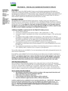
7 Some assumptions and generalizations can be made when designing triangular Swales , which simplify the design process. When the triangular swale cross section is split in half, two right angles are formed (Figure ). Figure Triangular swale cross section divided into two right angles. Dividing the swale into two right angles allows for some simplification of the swale design method. By the Pythagorean Theorem, the length of the unknown side x can be determined. In triangular Swales with 3:1, 4:1, or gentler side slopes, the length of x is found to be approximately the same as the length y. The y value is equal to half of the swale width; thus, the unknown distance x is also approximately equal to half the swale width. Because the wetted perimeter of a triangular swale is calculated as the sum of the two x distances seen in the figure above, the wetted perimeter is approximately equal to the swale width. When constructing a swale with known side slopes, the width of the swale can be defined in terms of the depth.
8 For example, 3:1 side slopes on a swale indicates that for every 1 foot of depth, each side slope will be 3 feet wide, for a total swale width of 6 feet. Also, we can define the area of the swale as: swale area = x width x depth With these geometrical assumptions, the equations used to size Swales can be simplified since the area and wetted perimeter terms can both be written in terms of depth in the hydraulic radius calculation. Therefore, the equations for triangular swale design are as follows: Equation 8-3: Manning s Equation for triangular Swales (side slope = 3:1) Qp = ( ) S1/2 Or D = [Qp n ( S1/2)] 69 Where: Qp = Peak Flow (ft3/s - section ) n = Manning s n value (Table ) D = swale depth (ft) S = swale slope (ft/ft) Equation 8-4: Manning s Equation for triangular Swales (side slope = 4:1) Qp = ( ) S1/2 Or D = [Qp n ( S1/2)] Equation 8-5 Manning s Equation for triangular Swales (sideslope = 5 to 1) Qp = ( ) S1/2 Or D = [Qp n ( S1/2)] Simplified triangular swale design process With the simplifications made to the Manning s equation for triangular Swales , the design process for these practices becomes straightforward.
9 In a basic design scenario, the slope (S) of the swale will likely be set. Likewise, the peak flow (Qp) from the catchment will be calculated using the rational method. Therefore, the depth of swale (D) and Manning s n will be the only unknowns once a given swale geometry is chosen. If space is available, side slopes of 4:1 or 5:1 can be used. This will allow easy access to the swale for mowing equipment. If limited space is available, 3:1 side slopes may be used. The design process requires iterations to achieve an acceptable design. In general, the steps of the design process are as follows: 1. Calculate peak flow for the 10 year storm from the catchment. 2. Determine slope from swale beginning to end. 3. Select swale geometry (typically 3:1 or 4:1 side slopes). 4. Assume Manning s n value from Table depending on chosen liner type. 5. Use equations 8-3, 8-4, and 8-5 to determine D, the depth of swale when flowing full during 10 year storm). 6. Use D to calculate swale area as define in Section Also calculate channel width as defined in Section make sure space is available if not, steeper side slopes may be used.
10 7. Use area calculated in step 6 and Qp to determine the velocity of the stormwater in the swale during the 10-yr storm (use Equation 8-1 - the continuity equation). 8. Compare velocity to permissible velocities in Table to determine if grass can withstand the velocity produced in the channel if so, the design is complete. 9. If grass cannot withstand the velocity produced in the channel, turf reinforcement matting can be used. If turf reinforcement matting is not desired, rock can be used; however, the design process must be repeated using a different Manning s n value. 70 Always perform a check to determine if the velocity produced in the channel can be passed by the channel lining without eroding. 10. If a safe velocity cannot be achieved with a given swale design, the slope of the system, the side slopes, or the liner type can be adjusted and the above calculations repeated. Construction Guidance Swales can be constructed using a variety of heavy equipment. The equipment used will depend on the size of the swale .