Transcription of 8-by-8 Bit Shift/Add Multiplier - Concordia University
1 8-by-8 Bit Shift/Add MultiplierGiovanni D AliesioID: 4860519 Digital Design & SynthesisCOEN 6501 Department ofElectrical & Computer EngineeringConcordia UniversityDecember 20038-by-8 Bit Shift/Add MultiplierGiovanni D Aliesio2 Table of Contents1 INTRODUCTION .. DESIGN 42 GENERAL REQUIREMENTS ..63 DESIGN SPECIFICATIONS .. CONTROLLER & MULTIPLICAND BLOCK & Multiplier /RESULT BLOCK & ADDER & Multiplier Bench .. & 164 DESIGN ENHANCEMENTS .. PLACE & DESIGN ADDER 32-BIT 215 CONCLUSION.
2 22 APPENDIX A: vhdl SOURCE 23 vhdl : : 25 vhdl : 28 vhdl : 30 vhdl : 34 vhdl : 36 vhdl : 32-BIT 38 vhdl : 32-BIT Multiplier 46 APPENDIX B: simulation RESULT FILES .. 48 APPENDIX C: SYNTHESIS REPORT FILES .. 51 APPENDIX D: PLACE & ROUTE REPORT FILES .. 568-by-8 Bit Shift/Add MultiplierGiovanni D Aliesio3 List of FiguresFIGURE 1-1: FPGA DESIGN 4 FIGURE 2-1: ADD/SHIFT Multiplier BLOCK 6 FIGURE 3-1: Multiplier DESIGN BLOCK 7 FIGURE 3-2: CONTROLLER FSM 8 FIGURE 3-3: CONTROLLER simulation timing 8 FIGURE 3-4: STRUCTURAL D 9 FIGURE 3-5: MULTIPLICAND 9 FIGURE 3-6: MULTIPLICAND simulation timing 10 FIGURE 3-7: MULTIPLIER_RESULT BLOCK 11 FIGURE 3-8: MULTIPLIER_RESULT REGISTER 11 FIGURE 3-9: MULTIPLIER_RESULT simulation timing 12 FIGURE 3-10: RIPPLE CARRY ADDER BLOCK 13 FIGURE 3-11.
3 CARRY SELECT ADDER BLOCK 13 FIGURE 3-12: RIPPLE CARRY ADDER simulation timing 14 FIGURE 3-13: CARRY SAVE ADDER simulation timing 14 FIGURE 3-14: TESTBENCH simulation BLOCK 15 FIGURE 3-15: COMPLETE Multiplier simulation timing 16 FIGURE 4-1: MINIMUM LATENCY timing 17 FIGURE 4-2: MAXIMUM LATENCY timing 18 FIGURE 4-3: DETAILED VIEW OF VIRTEX 19 FIGURE 4-4: COMPLETE 32-BIT Multiplier simulation timing 21 List of TablesTABLE 4-1: XILINX VIRTEX XCV50 DEVICE 19 TABLE 4-2: AREA & SPEED FOR VARIOUS ADDER 208-by-8 Bit Shift/Add MultiplierGiovanni D Aliesio41 INTRODUCTIONThe objective of this project is to go through a design cycle from initial conception to this case, it has been taken several steps further and synthesis as well as place & route was alsoachieved.
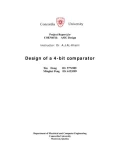
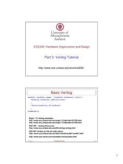
4 The goal is to design and simulate an 8-by-8 bit Shift/Add Multiplier . The result is acompletely synthesized 8-by-8 bit and 32-by-32 bit Shift/Add Multiplier with various designoptions for speed and Design FlowThe vhdl entry, simulation , synthesis and place & route was performed using a variety of highperformance, UNIX based CAD tools. The complete design flow is shown in Figure Visual EliteVHDL Entry&Initial SimulationModelSim SE vhdl simulation usingTest BenchSynplicity Synplify Design ManagerPlace & Route&Programming FileGenerationTarget DeviceXilinx Virtex XCV50bit file/mcs filereportfilesreportfilestestbenchoutpu tfilesMS Excelcompare results withexpectedFigure 1-1: FPGA Design Flow8-by-8 Bit Shift/Add MultiplierGiovanni D Aliesio5 Initial vhdl entry was done in Summit Visual Elite.
5 This tool provided the functionality tocompile the code and to perform initial simulation . The simulation performed at this level wasmainly to verify block level functionality and timing correctness. Once the blocks were coded andverified, a more advanced simulation tool was used, namely ModelSim. In this case, a completetest bench was developed which performed many multiplications and saved the result in a file was then compared to the expected results in order to confirm proper functionality. Uponsuccessful testing, the design was then synthesized using Synplicity s Synplify and thetechnology library for the Xilinx Virtex XCV50.
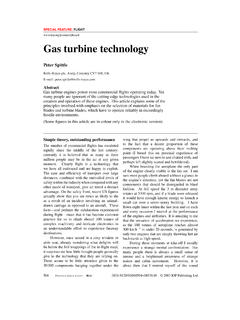
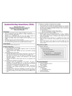
6 Finally, Xilinx Design Manager was used toplace and route the design, and generate the appropriate programming Bit Shift/Add MultiplierGiovanni D Aliesio62 GENERAL REQUIREMENTSThe requirement is to design an 8-by-8 bit Multiplier based on the shift and add method. Theoverall architecture is shown in Figure 2-1. The Multiplier shall accept as inputs an 8-bitmultiplier and 8-bit multiplicand as well as a Start signal. The Multiplier shall then calculate theresult using the shift and add method and provide the 16-bit result along with a Stop signal.
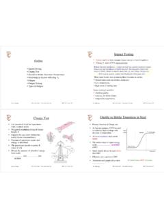
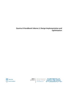
7 Thedesign shall be coded in vhdl and simulated for proper functionality and 2-1: Add/Shift Multiplier Block Diagram8-by-8 Bit Shift/Add MultiplierGiovanni D Aliesio73 DESIGN SPECIFICATIONSThe design was implemented using a mixture of both structural design and rtl level design. Ineach case the choice of style is described. The block diagram shown in Figure 3-1 details thebreakdown of vhdl modules. In the following sections each of the modules are described ingreater detail and associated diagrams, simulation outputs and timing are Ripple Carry AdderController8resetclkSTARTSTOPA_inB_i nRCMultiplier_ResultMultiplicand816 RARB888 Add_outC_outLSBLOAD_cmdMULTIPLIERSHIFT_c mdADD_cmdFigure 3-1: Multiplier Design Block Controller DesignThe Controller is the control unit of the Multiplier .
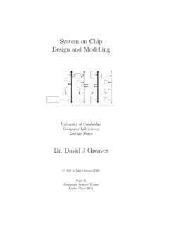
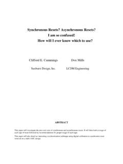
8 It receives a START signal and consequentlycommands all other modules until the result is obtained and it outputs a STOP DesignThe design was implemented as a finite state machine with states and transition logic as shown inFigure 3-2. The Start signal transitions the state machine out of the idle state and into the initializestate whereby it commands the multiplicand and Multiplier to be loaded into registers. Onceloaded, the state machine goes through a series of test and shift, or test, add and shift operationsdepending on the status of the LSB bit. Upon reaching the maximum count for the multiplicationcycle, the state machine goes back to the idle state and outputs a Stop Bit Shift/Add MultiplierGiovanni D Aliesio8 IDLESTOP = 1 INITLOAD_cmd=1 TESTADDADD_cmd = 1 SHIFTSHIFT_cmd =1count=count+1 START = 0 START = 1 LSB = 0 LSB = 1count /= 8count = 8 Figure 3-2: Controller FSM DiagramThe associated vhdl source code is included in Appendix A: vhdl Source simulation & TimingThe controller is synchronous to the clock and transitions through the various states occur on therising clock edge.
9 As can be seen from the timing diagram in Figure 3-3, the Start signaltransitions the state machine out of the idle state only when sampled by the rising clock entering the initialize state, the LOAD_cmd is generated. During each test state, the LSB issampled. If the LSB was high, the add state is entered and the controller generates the the LSB was low, or once the add state is exited, the shift state is entered and the controllergenerates the SHIFT_cmd. Upon reaching the maximum count for the multiplication cycle, thestate machine goes back to the idle state and outputs a stop 3-3: Controller simulation timing Diagram8-by-8 Bit Shift/Add MultiplierGiovanni D Multiplicand Block DesignThe Multiplicand block is composed of 8 D Flip-Flop blocks, which store the A byte forprocessing during the complete multiplication cycle.
10 The register is loaded with the LOAD_cmdsignal from the DesignThe basic design for the Multiplicand block is that of an 8-bit register. The top-level multiplicandmodule generates an 8-bit register from individual 1-bit D Flip-Flops. The individual D flip-flopshave been designed both structurally and behaviorally and the synthesized results are compared insection The structural design follows the diagram in Figure 3-4. The detailed diagram of theMultiplicand module is shown in Figure 3-5. The byte is loaded into the register only when theLOAD_cmd is received from the Controller and the register is cleared when a global reset D Flip-FlopclkresetDQFigure 3-4: Structural D Flip-FlopDFF7 DFF6 DFF5 DFF4 DFF3 DFF2 DFF1 DFF0 Multiplicand(8-Bit Register)A_in(7 downto 0)RA(7 downto 0)resetLOAD_cmdFigure 3-5: Multiplicand DiagramThe associated vhdl source code is included in Appendix A.