Transcription of 9.0 GENERATOR, EXCITER, AND VOLTAGE REGULATION
1 Emergency Diesel Generator The Generator, Exciter, and VOLTAGE REGULATION Rev 1/11 9-1 of 34 USNRC HRTD GENERATOR, EXCITER, AND VOLTAGE REGULATION This chapter presents the major components of the electrical generator, the exciter, and the VOLTAGE regulator and explains how they relate to the development of power by the diesel engine driven generator unit. Learning Objectives As a result of this lesson, you will be able to: 1. Describe the functions of the generator, exciter, and VOLTAGE regulator. 2. Identify the major components of the generator and how they inter-relate. 3. Describe how diesel engine output power relates to the power demands of the generator. 4. Describe the function of the excitation system and the associated VOLTAGE regulator. 5. Identity the major components of the exciter and VOLTAGE regulator system.
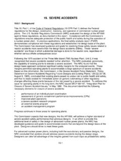
2 Generator Principles The following is a brief discussion of generator operation and its relationship to the mechanical load placed on the diesel engine. Electromagnetic Induction Electromagnetic induction, the basic principle of generator operation, involves the movement of an electrical conductor through a magnetic field . Figure 9-1 shows the principles being discussed in this section. As the conductor passes through the magnetic field , in this case downward, it cuts each of the lines of magnetic force (flux) which causes a current to be "induced" in the conductor. Because the conductor has a resistance, it is known from 'ohms law' that the VOLTAGE is equal to the current times the resistance. Therefore, a VOLTAGE is also 'induced' between the two ends of the conductor.
3 If the conductor is connected to a closed electrical circuit, this VOLTAGE would cause a current to flow. The amount of current flow is a function of the VOLTAGE induced and the electrical resistance of the load in the circuit. Induced VOLTAGE The actual VOLTAGE induced in the conductor is determined by the number of lines of flux cut per unit of time. Two key factors affect the magnitude of VOLTAGE induced. The speed at which the conductor moves through the fixed magnetic field and the strength of the magnetic field determine the output VOLTAGE . This speed is a function of the rotational speed (RPM) of the generator/engine. As the speed of the engine the generator increases, the VOLTAGE produced also increases. Since the operating speed of the engine and generator is constant in order to maintain the desired frequency, another method of VOLTAGE control must be employed.
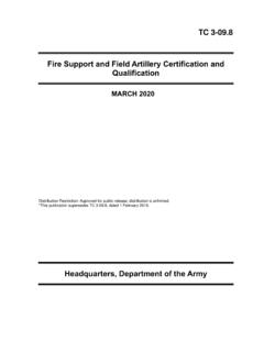
4 Generator output VOLTAGE is most often Emergency Diesel Generator The Generator, Exciter, and VOLTAGE REGULATION Rev 1/11 9-2 of 34 USNRC HRTD controlled by regulating the strength (flux intensity) of the magnetic field . This is accomplished by the generator excitation system. The excitation system monitors the generator output and regulates the magnetic field to maintain the desired VOLTAGE . As the load on the generator is increased, an increase in current flow causes the VOLTAGE to drop. The excitation system senses this decrease in VOLTAGE and increases the strength of the magnetic field to return the VOLTAGE to the desired level. How the generator works Figure 9-2 shows the principles discussed above implemented into a machine to produce a VOLTAGE . In this implementation, a U shaped form is provided with a gap between the open ends of the U.
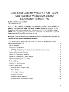
5 A coil of wire is wrapped about the legs of this form to produce a magnetic field across the gap. In the gap, an armature is formed by a loop of wire. The loop exits the armature onto two slip rings. The slip rings are contacted by brushes that connect the generator to the outside electric circuit. An engine or some other prime mover is connected to the armature causing it to rotate inside the gap. When the field coil is energized to establish a magnetic field /flux in the gap and the armature is then rotated, a VOLTAGE is generated in the armature. The slip rings and brushes conduct this VOLTAGE out to some load "A." Figure 9-3 shows a blowup of the armature in the gap. As the armature is rotated in its initial position, no VOLTAGE is created because the magnetic flux is equal but opposite on both branches of the loop. This is shown in the part of the diagram labeled 'Start.
6 ' As the armature is turned to a position 90 degrees from the first, the two ends of the loop is acted upon in a manner wherein the voltages generated at each end of the loop are additive, as shown in the '1/4-cycle' diagram. Peak output VOLTAGE is generated at each cycle point. As the armature continues to rotate, it again gets to a position of no VOLTAGE generation, shown in the -cycle diagram . As the rotation continues, a VOLTAGE is again generated. A close examination of the wiring out of the armature reveals that the connections have become inverted. This results in the opposite polarity of VOLTAGE . The diagram at the bottom of the figure shows the resulting build-up and decay and opposite polarity build up and decay again through two cycles (two rotations of the armature). The resulting VOLTAGE build-up and decay forms a sinusoidal wave that is defined as 'Alternating Current' or AC.
7 This is the basis for a single phase alternator. Two other sets of coils offset by 120 degrees and connected to slip rings would form a machine to generate 3-phase AC power. This is the basis for all AC 3-phase generation. If instead of using two slip rings a single ring that is split into two segments were used, as the armature rotated, there would be a buildup and decay of VOLTAGE as before; but the split slip ring would reverse the connection on each half revolution. The split slip ring configuration is commonly referred to as a 'commutator.' This would result in a machine that puts out a pulsating DC current. By combining a great many poles and the same number of segments Emergency Diesel Generator The Generator, Exciter, and VOLTAGE REGULATION Rev 1/11 9-3 of 34 USNRC HRTD on the armature commutator, an almost steady DC output would be produced.
8 This is the principle of the DC generator or motor. The AC alternator described above has a number of problems. The armature and its slip rings have to handle all the load current that is produced by this generator. The brushes and slip rings restrict the amount of current that can be handled. To eliminate this problem, design and construction were changed such that the small excitation current now goes through the brushes and slip rings to the rotating armature field . The large AC current induced into the stationary stator windings is transmitted to the loads by solid connections. This same principle also applies to AC synchronous motors as there is little difference between an AC generator and an AC synchronous motor. It is a matter of what is driving the system an electric motor or an engine-driven generator.
9 This also simplifies the construction of the generator. These machines very often also are called 'alternators' in as much as the VOLTAGE and current are alternating. A three-phase generator/alternator is simply three single phase machines interlaced with one another, sharing the same rotor assembly, with wiring brought out to connect each phase into the electrical system. The result of the interlacing of the alternator windings is shown on the VOLTAGE trace shown at the bottom of Figure 9-4. The upper part of Figure 9-4 shows how the current of each/any phase acts to produce the power. The left-most diagram shows the current in phase with the VOLTAGE . This is the case when the power factor is (unity). The real power (KW) in that case is equal to the apparent power (KVA). These terms will be discussed later.
10 When the current is not in phase with the VOLTAGE , there is a lesser power factor, and the KW is less than the KVA. The KW is still in phase with the VOLTAGE , but the KVA has shifted slightly due to the shift in the current. This introduced KVAR, and will be explained later. Generator Construction Figure 9-5 shows a cutaway of a typical generator. The generator consists of a shaft on which is mounted a hub, more often called the spider. The spider may be attached to the shaft by a press fit, with or without keys, or by a flange and bolting. The spider has slots into which the field pole pieces are attached. Together, this makes up the rotor . The rotor assembly usually also includes slip rings used to convey the field current into the field windings. These windings are wrapped around the pole pieces.