Transcription of 9. DG SET SYSTEM
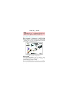
1 9. DG SET SYSTEM165 Bureau of Energy EfficiencySyllabusDiesel Generating SYSTEM :Factors affecting selection, Energy performance assessment ofdiesel conservation IntroductionDiesel engine is the prime mover, which drives an alternator to produce electrical energy. Inthe diesel engine, air is drawn into the cylinder and is compressed to a high ratio (14:1 to25:1). During this compression, the air is heated to a temperature of 700 900 C. A meteredquantity of diesel fuel is then injected into the cylinder, which ignites spontaneously becauseof the high temperature. Hence, the diesel engine is also known as compression ignition (CI)engine. DG set can be classified according to cycle type as: two stroke and four stroke. However,the bulk of IC engines use the four stroke cycle. Let us look at the principle of operation of thefour-stroke diesel Stroke - Diesel Engine The 4 stroke operations in a diesel engine are: induction stroke, compression stroke, ignitionand power stroke and exhaust :Induction stroke - while the inlet valve is open, the descending piston draws infresh :Compression stroke - while the valves are closed, the air is compressed to a pressure ofup to 25 :Ignition and power stroke - fuel is injected, while the valves are closed (fuel injectionactually starts at the end of the previous stroke), the fuel ignites spontaneously andthe piston is forced downwards by the combustion :Exhaust stroke - the exhaust valve is open and the rising piston discharges the spentgases from the Schematic Diagram of Four-Stroke Diesel Engine9.
2 DG Set System166 Bureau of Energy EfficiencySince power is developed during only one stroke, the single cylinder four-stroke engine hasa low degree of uniformity. Smoother running is obtained with multi cylinder engines becausethe cranks are staggered in relation to one another on the crankshaft. There are many variationsof engine configuration, for example. 4 or 6 cylinder, in-line, horizontally opposed, vee or radi-al Set as a SystemA diesel generating set should be considered as a SYSTEM since its successful operation dependson the well-matched performance of the components, namely:a)The diesel engine and its )The AC )The control systems and )The foundation and power house civil )The connected load with its own components like heating, motor drives, lighting is necessary to select the components with highest efficiency and operate them at theiroptimum efficiency levels to conserve energy in this DG Set SystemSelection ConsiderationsTo make a decision on the type of engine, which is most suitable for a specific application,several factors need to be considered.
3 The two most important factors are: power and speedof the engine. The power requirement is determined by the maximum load. The engine power ratingshould be 10 20 % more than the power demand by the end use. This prevents overload-ing the machine by absorbing extra load during starting of motors or switching of sometypes of lighting systems or when wear and tear on the equipment pushes up its is measured at the output shaft and given in revolutions per minute (RPM). Anengine will operate over a range of speeds, with diesel engines typically running at lower9. DG Set System167 Bureau of Energy Efficiencyspeeds (1300 3000 RPM). There will be an optimum speed at which fuel efficiency willbe greatest. Engines should be run as closely as possible to their rated speed to avoid poorefficiency and to prevent build up of engine deposits due to incomplete combustion - whichwill lead to higher maintenance and running costs.
4 To determine the speed requirement ofan engine, one has to again look at the requirement of the some applications, the speed of the engine is not critical, but for other applicationssuch as a generator, it is important to get a good speed match. If a good match can beobtained, direct coupling of engine and generator is possible; if not, then some form of gear-ing will be necessary - a gearbox or belt SYSTEM , which will add to the cost and reduce are various other factors that have to be considered, when choosing an engine fora given application. These include the following: cooling SYSTEM , abnormal environmentalconditions (dust, dirt, etc.), fuel quality, speed governing (fixed or variable speed), poormaintenance, control SYSTEM , starting equipment, drive type, ambient temperature, altitude,humidity, etc. Suppliers or manufacturers literature will specify the required information when purchasingan engine. The efficiency of an engine depends on various factors, for example, load factor (per-centage of full load), engine size, and engine type.
5 Diesel Generator Captive Power PlantsDiesel engine power plants are most frequently used in small power (captive non-utility) sys-tems. The main reason for their extensive use is the higher efficiency of the diesel engines com-pared with gas turbines and small steam turbines in the output range considered. In applicationsrequiring low captive power, without much requirement of process steam, the ideal method ofpower generation would be by installing diesel generator plants. The fuels burnt in dieselengines range from light distillates to residual fuel oils. Most frequently used diesel engine sizesare between the range 4 to 15 MW. For continuous operation, low speed diesel engine is morecost-effective than high speed diesel of adopting Diesel Power Plants are: Low installation cost Short delivery periods and installation period Higher efficiency (as high as 43 45%) More efficient plant performance under part loads Suitable for different type of fuels such as low sulphur heavy stock and heavy fuel oil incase of large capacities.
6 Minimum cooling water requirements, Adopted with air cooled heat exchanger in areas where water is not available Short start up timeA brief comparison of different types of captive power plants (combined gas turbine andsteam turbine, conventional steam plant and diesel engine power plant) is given in Table can be seen from the Table that captive diesel plant wins over the other two in terms ofthermal efficiency, capital cost, space requirements, auxiliary power consumption, plantload factor DG Set System168 Bureau of Energy EfficiencyTABLE COMPARISON OF DIFFERENT TYPES OF CAPTIVE POWER PLANTD escriptionUnitsCombinedConventionalDiese l EngineGT & STSteam PlantPower PlantsThermal Efficiency%40 4633 3643 45 Initial Investment ,500 10,00015,000 18,0007,500 9,000 Installed CapacitySpace requirement125 % (Approx.)250 % (Approx.)100 % (Approx.)Construction timeMonths24 30 42 48 12 15 Project periodMonths30 3652 6012 Auxiliary Power%2 48 - Load FactorkWh/kW6000 70005000 60007200 7500 Start up time from coldMinutesAbout 10120 18015 20 Diesel Engine Power Plant DevelopmentsThe diesel engine developments have been steady andimpressive.
7 The specific fuel consumption has comedown from a value of 220 g/kWh in the 1970s to a valuearound 160 g/kWh in present speed diesel engine, with its flat fuel consump-tion curve over a wide load range (50% 100%), comparesvery favourably over other prime movers such as mediumspeed diesel engine, steam turbines and gas the arrival of modern, high efficiency tur-bochargers, it is possible to use an exhaust gas driventurbine generator to further increase the engine rated out-put. The net result lower fuel consumption per kWhand further increase in overall thermal efficiency. The diesel engine is able to burn the poorest qualityfuel oils, unlike gas turbine, which is able to do so withonly costly fuel treatment speed dualfuel engines are now available usinghigh-pressure gas injection, which gives the same thermal efficiency and power output as a reg-ular fuel oil Selection and Installation FactorsSizing of a Genset:a)If the DG set is required for 100% standby, then the entire connected load in HP / kVAshould be added.
8 After finding out the diversity factor, the correct capacity of a DG setcan be found Turbocharger9. DG Set System169 Bureau of Energy EfficiencyExample :Connected Load=650 kWDiversity Factor= (Demand / connected load)Max. Demand=650 x = 350 kW% Loading=70 Set rating=350 = 500 kWAt PF, rating=625 kVAb)For an existing installation, record the current, voltage and power factors (kWh / kVAh)reading at the main bus-bar of the SYSTEM at every half-an-hour interval for a period of2 3 days and during this period the factory should be having its normal operations. Thenon-essential loads should be switched off to find the realistic current taken for runningessential equipment. This will give a fair idea about the current taken from which therating of the set can be existing installation:kVA= 3 V IkVA Rating= kVA / Load Factorwhere Load factor= Average kVA / Maximum kVAc)For a new installation, an approximate method of estimating the capacity of a DG set isto add full load currents of all the proposed loads to be run in DG set.
9 Then, applying adiversity factor depending on the industry, process involved and guidelines obtainedfrom other similar units, correct capacity can be arrived Speed Engine or Slow/Medium Speed EngineThe normal accepted definition of high speed engine is 1500 rpm. The high speed sets have beendeveloped in India, whereas the slow speed engines of higher capacities are often imported. Theother features and comparison between high and medium / slow speed engines are mentioned below:FactorSlow speed engineHigh speed engineBreak mean effective pressure - thereforeLowHighwear and tear and consumption of sparesWeight to power ratio- therefore sturdinessMoreLessand lifeSpaceHighLessType of useContinuous useIntermittent usePeriod between overhauls*8000 hours3200 Direct operating cost (includes lubricatingLessHighoils, filters etc.* Typical recommendations from manufacturersKeeping the above factors and available capacities of DG set in mind, the cost of econom-ics for both the engines should be worked out before arriving at a DG Set System170 Bureau of Energy EfficiencyCapacity CombinationsFrom the point of view of space, operation, maintenance and initial capital investment,it is certainly economical to go in for one large DG set than two or more DG sets in or more DG sets running in parallel can be a advantage as only the short-fall inpower depending upon the extent of power cut prevailing - needs to filled up.)
10 Also, flexibilityof operation is increased since one DG set can be stopped, while the other DG set is generatingat least 50% of the power requirement. Another advantage is that one DG set can become 100%standby during lean and low power-cut Cooling Vs. Water CoolingThe general feeling has been that a water cooled DG set is better than an air cooled set, as mostusers are worried about the overheating of engines during summer months. This is to someextent is true and precautions have to be taken to ensure that the cooling water temperature doesnot exceed the prescribed limits. However, from performance and maintenance point of view,water and air cooled sets are equally good except that proper care should be taken to ensurecross ventilation so that as much cool air as possible is circulated through the radiator to keepits cooling water temperature within , it may be possible to have air cooled engines in the lower capacities, it will be nec-essary to go in for water cooled engines in larger capacities to ensure that the engine does notget over-heated during summer FeaturesIt is advisable to have short circuit, over load and earth fault protection on all the DG , in case of smaller capacity DG sets, this may become uneconomical.